Monday, October 7, 2013

Lightning-protection system

Earthing


In Malta (and I assume in most, if not all countries), earthing is mandatory. This is provided by the mandatory earth electrode which must be located next to the power meter. For redundancy sake, I have added a further two earth electrodes, all installed (dug) in different locations. In fact the additional electrodes have been installed in the yard. All the electrodes are interconnected using 6mm copper cable to maintain the same earth potential.
A 10mm cable runs from the electrodes to the roof were I have all the photovoltaic panels, panel structures and wind turbine earthed.

To protect all my house electrical and electronic equipment, I have constructed a number of lighting protection circuits. These are;

1) Circuit to protect my mains supply - 240v AC 50Hz, being supplied either from my local power provider (Enemalta) or from the inverter.
2) Circuit to protect my 24v DC house wiring system.
3) Circuit to protect power from the 'off-grid' panels feeding the batteries and off-grid inverter.
4) Circuit to protect power from the 'grid-tie' panels.

1) Circuit to protect my mains supply, being supplied either from my local power provider (Enemalta) or from the inverter.
The basic and most important component is the Varistor, and in fact I have used quite a number of them.
Surge protection is provided between;
a. Live <--> Neutral. This is the most important and in fact most electronic equipment will be already protected internally using a similar setup.
b. Live <--> Earth. This is also very important to protect since the potential difference between Neutral and Live should be close to the potential difference between Live and Earth.
c. Neutral <--> Earth. The voltage difference between Earth and Neutral should be close to 0 because the Neutral is actually earthed at the distribution centre. However a small potential difference does exist (<10v) and this protection is intended to safeguard in case the Neutral potential is raised with respect to the Earth.

Components List
SA1, SA2: Miniature Gas Filled, 20kA/20A
C1, C2, C3: 150nF 300v AC Capacitors
RV1-RV5: 300v Varistors
RV6-RV10: 300v Varistors
RV11-RV15: 30v Varistors
D1: Green LED
R1: 150K 0.25w

2) Circuit to protect my  24v DC house wiring system.
The below circuit is used to protect against any surges which might get through to the DC system (batteries, off-grid inverter, house lights etc). Protection is mainly provided by the varistors, however diodes D1 and D2 are connected in reverse polarity across the supply to protect against any back emf.

Components List
C1: 100nF
C2: 4700uF 50v
RV1-RV5: 30v Varistors
D1: Green LED
R1: 1.5K 0.25w
D2, D3: 10Amp Diodes

3) Circuit to protect power from the 'off-grid' panels.
This circuit sits exactly under the off-grid panels and serves as the primary protection to my DC system against any voltage surges/spikes.
Components List
C1, C2, C3, C4: 4700uF 50v
RV1-RV2: 50v Varistors
D1, D2: 10Amp Diodes
F1, F2: 5 amp fuses

4) Circuit to protect power from the 'grid-tie' panels.
This circuit sits exactly between the grid-tie panels and the grid-tie inverter. It was not really necessary because this type of circuit already exist internally in the inverter however I wanted to provide extra external protection. I prefer this circuit blowing up then my expensive SMA inverter!


Components List
C1: 470uF 400v
C2: 100nF 1000v
RV1-RV3: 360v Varistors
D1: 10Amp Diode

Friday, July 26, 2013

Differential Controller (extension)

Scope


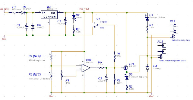
The scope of this circuit is to use my existing Steca TR0301 differential controller, but connected to two heat sources (log fireplace and solar collector) and two circulating pumps. The simple circuit below will enable me to continue using the TR0301 controller while at the same time reading temperature from two heat sources and controlling two independent circulating heat pumps. The storage tank is the common factor.
 
Details of how I'm capturing escaped heat from the fireplace can be found here

Background

In Malta, the log fireplace is only switched on for a maximum of three months (at least in my case) and therefore I couldn’t justify purchasing another differential controller just to be used for only three months. Also, I do not light the fireplace during the day when the solar collector is working. In fact the solution I’ll be explaining can only have one heat source active at a time.

The circuit has been built to be reliable using the least number of electronic components. Since the majority of the time the controller will be controlling heat from the solar controller, the circuit has been designed to be ‘off’ the majority of the time, i.e. the relays de-energised.   

Circuit Description 


The circuit is powered from the house 24v DC supply. This is stepped down using IC1 7812 linear voltage regulator. IC1 is fed via fuse F1 and diodes D1and D6 protect the circuit in case of a polarity reversal. Capacitors C1 and C2 provide supply smoothing while the green LED D2 indicates that the 12v supply is available.

The circuit is based on the quad opamp LM324. In this application I’ll be using only one of the four opamps. Pin 6 (Inverting input) is pre-set to approximately half the supply voltage *, while Pin 5 (non-inverting input) is set by thermistors R6 and R7. These thermistors are identical 47K NTC type located at the solar collector and the other attached to the chimney pipe. NTC thermistors reduce resistance once the temperature is raised.

Two scenarios are available;

1)      R6 > R7 i.e. Solar Collector warmer than Fireplace.

When the solar collector is warmer than the fireplace, the resistance of R6 will be less than R7 and therefore Pin 5 is taken to Ground. Assuming Pin 6 set to 6v (half the supply voltage), and therefore Pin 6 voltage is higher than Pin 5, the opamp output will be low. Transistor TR1 is OFF and both relays OFF. While OFF,

·         RL1 will be connecting the differential controller to the solar circulating pump

·         RL2 will be connecting the  differential controller to the Steca PT1000 temperature sensor located at the solar collector

2)      R7 > R6 i.e. Fireplace warmer than Solar Collector.

When the fireplace is warmer than the solar collector, the resistance of R7 will be less than R6 and therefore Pin 5 is taken high to the supply voltage. Assuming Pin 6 is set to 6v (half the supply voltage), Pin 5 voltage is higher than Pin 6; the opamp output will be high. Transistor TR1 is ON and both relays are ON.

·         RL1 will be connecting the differential controller to the fireplace circulating pump

·         RL2 will be connecting the differential controller to the Steca PT1000 temperature sensor located at the fireplace chimney.
 
*  Voltage at Pin 6 is set depending on the length of wire between the individual thermistors and the circuit. In my case, the length of R6 is more than 4 times the length of R7 and therefore I had to compensate using potentiometer R8.

Saturday, May 18, 2013

Greywater System (Update 2)

With reference to my first greywater system which I built a year ago, I can post my review and any changes I made to make the system more efficient.

Well, the first system worked but did not work as well as I hoped for. The problem was mainly the amount of time needed for the system to filter the 100 litre storage tank. Before building the system, I had tested and concluded that a 100 litre would be filtered in a couple of hours. The parallelism of 3 streams which I included should have achieved good results however to my disappointment, it was taking far too long to filter and therefore I was wasting water down the drain.

To speed up the filtration process and not rely solely on gravity I installed a pump. The pump will take water from the buffer tank and pressurise it into the sand filters. At least that was my intention until I installed it and switched it on. After 30 seconds, I identified 5-8 leaks and suddenly one of the sand filters exploded, specifically one of the bottom screwable taps came off together with all the sand! Not much to do. It was obvious that the system coundn't handle any pressure. The drain pipes which I originally used were not the heavy-duty type and I never imagined that a tap would just explode outwards. At this stage I had two options:

1)      Fix the exploded filter (strengthen also the other two) and maybe use PVC glue to fasten the taps once and for all. The problem will be that the sand inside will not be replaceable anymore, something which I didn’t want!

2)      Replace the filters.

I opted for the second option. Although option 1 would have probably worked, I did not want to spend time experimenting with this solution hoping that finally I have no leaks/explosions


 System Overhaul

The changes were mainly at the filtration stage. Both tanks and all plumbing were OK. I scrapped the sand filters and installed four 10 inch standard water filter housing.

The first filter I’ve installed is just after the storage tank, before feeding the pump. It’s a 25 micron wound filter cartridge and its main purpose is to stop particles entering the pump.

The other three filters I’ve installed just after the pump i.e. will be benefitting from the increased pressure. The filters are also the 10 inch cartridges. The filters are;

1)      15 micron active carbon

2)      5 micron

3)     1 micron   

The pump is automatically activated using a float switch installed in the tank and therefore is only active if the tank is full.


Friday, May 10, 2013

Diversion load circuit


Scope

The circuit below has been designed to control the amount of charging applied to my house forklift batteries, while diverting the ‘not used’ power to a small grid-tie inverter. The circuit has been kept simple, minimising cost and making trouble shooting easier in case of problems.

Please refer to the Off-Grid System Update Post for more details.


Circuit Description

The relays contacts have been connected in a way to automatically (while de-energised) route the power to the batteries. Therefore if the batteries are low, no power is wasted to power the circuit/relays! Once the battery voltage starts rising, the circuit will come on, the relays will energise incrementally (depending on the threshold voltages) and power is redirecting from the batteries to the inverter.

Power from the arrays is fed via diodes D10, D11, D12 & D13 to power the circuit itself. The voltage is fed to IC1 - 7812, a linear voltage regulator via dropping resistor R21. The voltage is stepped down to a stable 12v which is used to power the opamps and relays. R21 was needed because the 7812 maximum input voltage is about 35v. This is a bit low considering the voltage coming in from the panels which can reach even 45v (Uoc). Resistor R21 will reduce the input voltage to 20-30v which is within the regulator input operating voltage. Diodes D14 and D15 will increase the regulator voltage by a further 1.4v thus getting around 13v (no load) from the regulator. The circuit voltage is further smoothed and stabilised by capacitor C1, C6 and C7. Varistor RV1 clamps the maximum voltage to 14v.  
The basic principle behind the circuit is simple. Switching is performed by comparing the battery voltage to a fixed reference voltage. Different thresholds have been pre-set thus switching power incrementally at fixed intervals. The four opamps found in the LM324 chip (IC2) have been configured as comparators.

The fixed reference voltage is provided by IC3A. The opamp configuration outputs a very stable 10v through resistor R9. This fixed voltage is applied to the inverting input of IC2 four opamps.
The circuit has got four distinct comparators IC2A, B, C, and D. Since all four are identical, I’ll write only about IC2A. Voltage from the battery is taken via potentiometer POT1 through resistor R20. This voltage is stabilised by resistor R19 and capacitor C11. This will eliminate any sudden voltage fluctuations (which may be caused by sudden huge loads on the batteries or clouds passing over the panels) thus reducing unnecessary switching of the arrays. Further switching stabilisation is also provided at the output of the comparator via resistor R1 and capacitor C2. When the voltage at the non-inverting input (Pin 3 – Connected to the battery sense) is higher that the inverting input (Pin 2 – connected to the reference voltage), the opamp switches on. This will bias the transistor TRN1 which will energise relay RLY1.Once energised; the relay will direct the access power to the grid tie inverter. Diode D1 protects the transistor TRN1 against the relay coil back emf, while LED D5 signals the relay state.

The circuit has been calibrated to divert power at specified battery voltages. These have been set at 27v, 28v, 29, and 30v.


Wednesday, April 3, 2013

Cordless telephone charger (Battery Backup)


Scope

Cordless phones are great! Without going into all their benefits I really like their grid power independence, but there is one problem. Although the cordless phones work on batteries, the base station (and all connecting phones) becomes useless in case of a power failure since the base station needs power to work! To overcome this limitation, I designed and built a simple circuit which powers the base station with the benefit of battery backup.
Although I could have easily tapped a 24v or 12v supply to power the base station from the house batteries, I had a problem with this setup because basically the base station stopped working. In my scenario, I’m also powering the telephone provider modem using my in-house batteries instead of the supplied power adaptor. It seems that the power used for the modem has to be isolated from the power used for the base station. Don’t know why this is but that’s how it has to be!

The requirement was to build a small power supply of 6.5v at a maximum current of 350mA. These are the ratings of the power supply which came with the phone. Here are more details of the phone system and how I'm charging the phones using solar energy.

How it works


AC power is supplied from a 16v ac power adapter, rectified by diodes bridge B1 and smoothed by capacitor C1. LED D8 indicates that the ac power is available. This voltage is then applied to voltage regulator U1, the 1 amp regulator 7812 through diode D1. Diodes D2, D3& D4 will boost U1 output voltage by 0.7v increments and therefore the output from U1 is 13.8v. This is fed to an external battery through fuse F2. The 13.8 volts is enough to keep the battery fully charged or better trickled charged. If this voltage is too high, it can be decreased by removing diodes D2, D3, D4, each diode decreasing the voltage by 0.7 volts.

Diode D5 will direct combined power from the power supply and battery to another voltage regulator U2, the 1 amp regulator 7808.  Diode D5 reduces the voltage and linear regulator U2 will stabilise the voltage to 8v. This is smoothed by capacitor C2 and further reduced by diodes D6 & D7 to 6.8v which is the base station operating voltage. LED D10 indicates that power is being fed to the base station.

Monday, January 21, 2013

Fireplace water heating system (Part 1)

Fireplace water heating system (Part 1)
 
A couple of years ago, we installed a log fireplace at home, a 13KW box from Rotin fires of Zabbar. I'll try to find and post the brand and specification details of the firebox. We light it up only for 3-4 months a year, starting in November/December till March.
These are obviously the worst months for heating water from the sun simply because the days are the shortest and temperatures are the lowest. In fact, during this period we have a deficit of hot water from our water solar heater and we need to boost it up with the electric heating element.
This is why I decided to explore the possibility of heating my solar water tank using escaped heat from the fireplace.
 
The pictures below show what I did to capture heat from the fireplace.
 

The above pictures are a 0.5 metre section of the chimney with a 15 metre half inch copper pipe wound around it. The idea is to capture heat escaping from the chimney pipe and getting it absorbed in the liquid circulating in the copper pipe which will eventually heat up the hot water tank. 


Getting the copper pipe around the chimney pipe proved to be a tough job; in fact I needed help from my two little boys :)

Once the copper pipe was properly wound and secured to the chimney pipe, I used a blanket to insulate the copper pipe from the outside air, thus decreasing heat losses.


The below pictures show the final result. The blanket has been further covered with fibre-glass to further insulate and protect against the elements.

 
I'll be posting another article with all the details of the plumbing and circulating pump once I have everything installed and working.

Monday, January 14, 2013

Off-Grid System (Update)

 
Off-Grid System Upgrade.
 
Thanks to an EU competition, the European Citizens Climate cup , which came to end last May (2012), me and my family placed 2nd with just a 0.5% less reduction in electricity consumption than the winner. I still was awarded €1000 cash to be spent on Renewable Energy stuff. My natural choice was more solar panels :)
I had been planing to upgrade my off-grid system consisting of only 320W of panels for quite some time now and this reward was more than welcome. With the money, I purchased 4 solar panels - IBC Monosol 190MS from Crosscraft. This upgrade of 760W was to increase my off-grid system power production to an STC of 1080W.
The picture below is displaying the mouting of the new panels. These have been mounted horizontally and fitted exactly across the roof. 


Another picture of the new panels as taken from above. The new panels are fixed just in-front of the other grid-tie system panels.


With a new off-grid power generation of 1 KW, I wanted to make sure that no power is wasted once the batteries are full. This can easily happen in Spring and Summer when the days are longer and the load is lower. (Please refer to my separate article titled Off-Grid System for a list of loads being supplied from this setup).
To cater for this access energy, I installed a new 500W grid-tie inverter. This inverter is capable of accepting directly the power from the panels mentioned above and export the power to the grid. In fact the input voltage for this inverter is low (28v - 52v).


My off-grid panels are wired in parallel in 4 groups. The left most DC amp meters records the power coming in from the seperate groups.

 
Group Details:
  • 2 Sharp panels x 80W each = 160W
  • 2 Sharp panels x 80W each = 160W
  • 2 IBC panels x 190W each = 380W
  • 2 IBC panels x 190W each = 380W
To control when and how much to export to the grid, I needed a way of determining the batteries state of charge. I did this by simply monitoring the battery voltage and switching on the panels when the battery voltage is low while diverting the panels to the grid once the battery voltage reaches a pre-determined high voltage. The circuit below does just that! It monitors the battery voltage in these steps;
  • at 27v. Diverts the first 160W to the grid-tie inverter
  • at 28v. Diverts the second set of 160W to the grid-tie inverter
  • at 29v. Diverts the first 380W to the grid-tie inverter.
  • at 30v. Diverts the second 380W to the grid-tie inverter. This actually switches off all charging from the solar panels.
Once the battery voltage goes down again, the circuit will disconnect the panels from the grid inverter and direct the current back to the batteries in reversing order.

As can be easily noted, the export inverter is rated at 500W (Max) while I have double in solar power. Although all panels can be automatically diverted to the inverter, the inverter is only capable of exporting 500W. I know about this limitation and in fact I have left space for a second identical inverter to be installed right below the first.
Being in Winter, I don't have much access energy to export, and in fact the max exported I noticed was 320W and occasionally the first set of IBC panels.

The pictures below is the switching circuit used to control the batteries charging and load diversion. Notice the 4 relays, used to switch the 4 seperate groups of solar panels.


I'll be posting a seperate article to describe how the above circuit works.