Thursday, April 20, 2023

Battery Monitoring System

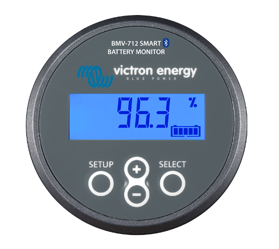
One of the first tasks I assigned myself on purchasing the yacht was to install a battery monitoring system. After some research I opted for the Victron BMV-712 Smart monitor. This model has Bluetooth built in which is a huge benefit considering that you can access the monitored data from the comfort of the mobile.


I have installed the 500amp shunt just next to the batteries, keeping the wires as short as possible. I have used 70mm wire (as what has been initially installed by the manufacturer).


The Smart monitor display has been installed on the chart table. I located an empty surface and installed some other stuff as well (as seen below). 
    - DC Battery monitoring system
    - AC Monitoring system
    - USB Ports
    - AC Power Ports


The datasheet for the Smart monitor can be downloaded from here

I'm also attaching a Current Cable Rating chart which I found online for reference.

Inverter Installation

There are a lot of inverters out there however hands down I bought the Outback Inverter (Marine - sealed, Export version 12v DC to 230v AC). I can vouch for these inverters! I already have an off-grid 24v inverter installed at home and it delivers what it promises. Weighting a whopping 30kg, one can easily acknowledge how robust these inverters are built.


I found this photo on the web. It can be clearly seen why the inverter is so heavy. Bottom right there seems to be a huge transformer.


Some Basic stats;
    Pure Sinewave
    DC 12v Input 
    AC 230v Output
    Continuous power 2000VA which can surge to 4600VA for 100ms.

The inverter has been connected using 70mm marine grade cable which is good enough to handle the DC current with minimal voltage drop. Please refer to the wire chart at the bottom of this post.
The inverter has been protected by a 120amp circuit breaker. I'm limiting the current which the inverter can draw to 120amp or 10amp AC on the high side which is more then enough for my needs. The inverter can also be switched off when not needed (to eliminate the standby current drain on the batteries). The battery switch has been overrated and in fact can handle 275amp. This will ensure a longer switch life since it will not be operating at to it's maximum ratings.


The Inverter switch (left) has been fitted next to another 3 main switches which I fitted myself. The middle switch is used to connected another set of deep cycle batteries situated at the stern of the boat. I covered these batteries in a separate post. The right switch is used to disconnect the solar panels.


The Inverter circuit breaker has been fitted under the main saloon seat just next to the inverter.


Below are the pictures showing the inverter installation and location. It has been fitted to the boat although considering it's weight it won't move easily.
The location is underneath the starboard saloon seats.


The load which I'll be powering with these inverter are;
  • 900W Toaster
  • 1200W Electric Kettle
  • 240v AC points
  • Small (10litre) air compressor
  • 240v Water pump (used to flush the black water tanks & Deck wash)
Obviously I won't be powering all these loads at once.


Below is a Cable Rating chart which I use to select my DC wire sizes.


Some related documents.


Water Expansion Tanks

Why install an expansion tank?

Well the answer depends if it's installed on either the cold or water circuit.

  • Cold circuit.

On the cold circuit, an expansion tank is not really indispensable however I installed it because it will reduce the number of times the water pressure pump switches on. The pump will not switch on every time the water tap is opened. Once it's on, it will fill up the expansion tank (depending on the size of the installed expansion tank) and any subsequent water usage is supplied from the tank until the pressure falls enough that the pump will need to switch on. 

The installation of this expansion tank is a huge benefit especially at night because the pump will not switch on as soon as the water tap is opened. The pump although enclosed is not very silent and at night it just wakes everyone up when it switches on!

  • Hot circuit
In this case, personally I think that an expansion tank is indispensable. The expansion tank is designed to handle the thermal expansion of water as it heats up in the water heater, preventing excessive water pressure. If water pressure gets to high it can damage valves in plumbing fixtures, joints in supply pipes and the water heater itself.
I installed both expansion tanks at the bow of the boat (the location of the tanks is irrelevant) specifically in the master forward cabin, next to the bow thruster.
As seen below, the small hot water expansion tank is connected through a red pipe, through a Tee in the how water circuit.  


The cold water expansion tank is also installed at the bow in the bow thruster compartment. 


The expansion tank is the left most white tank. it's connected using a blue pipe through a Tee in the cold water system. On the right you can notice the RO system.


Fridge Extra Cooling

One way to increase a fridge efficiency i.e. consume less power while maintaining a low temperature is to keep the compressor and the condenser coils as cool as possible and this can be achieved by facilitating heat dissipation. 
As detailed below, the Condenser Coils need to dissipate heat efficiently to enable the refrigeration process to function efficiently.
This is normally achieved using natural air ventilation and one way of doing this is by leaving enough space for the compressor and condenser coils to breath and release heat naturally.
In fact, house appliances, the manufacturer recommends the clearance which should be kept between the appliance and the surroundings enclosure.

Having a look at the location of the fridge and subsequent compressor / condenser coils, there is not much space for natural air cooling simply because the assigned space has very little way of ventilating since the cabinet volume is very slow.


To overcome this, I installed a 12mm silent fan (as seen below). The fan will extract the heat from the compressor and condenser (installation unit) and push it out to the next cabinet on the right i.e. another small cabinet under the oven. 
The overall volume has now increased however this will not really help much since the extended cabinet is also sealed with little ventilation.


To fix this also, I drilled a 12mm hole on the upper section of the adjacent cabinet i.e. just underneath the oven.
Since warm air flows up, this will ensure that the heat will escape from this hole, thanks to the external fan which is pushing it out.


The system operation is very simple. I took the supply directly from the compressor connections, i.e. the external fan will switch off when the compressor is off. 
I also installed a 45 degrees thermal switch on the compressor and therefore the external fan will only come on once the compressor is busy working and has reached 45 degrees +
The extra fan does add more noise to the fridge operation however it will switch on only when the compressor is on and hot.


The connections have been installed in a waterproof box just next to the compressor.


A further improvement which I'll be making soon is to drill a hole at the bottom of the air compressor cabinet thus 'cooler' air will be sucked up from the bilges.

ps. Always make sure that the condenser coils are free any dust since this may/will act to to reduce heat dissipation, lowering the overall system efficiency.