Friday, August 25, 2017

24v System Upgrade

Part of my home system overhaul, I also upgraded the 24v panel. 10 years ago when I first built the control panel, my system requirements were much less. 

The photo below is displaying my old control panel. I have 4 amp meters together with their respective fuse holders and switches.
The fuse holders were rated for 5 amp and the switches for 10 amp DC, however during the years, I had issues with both since I had to replace multiple switches and fuse holders because they melted


The photo below is displaying the new control panel. I removed the switches because in 10 years I don't think that I ever needed to switch off a PV string. Also, I removed the panel mount fuse holders, and instead I opted for a heavier duty rail mount fuse holders which have been installed inside the control box. I also replaced all analogue amp meters and analogue voltmeters with digital meters. The only amp meter which is still analogue is the wind turbine amp meter.
I now have 5 amp meters or PV string. Three of the string will feed directly the batteries while the other two strings will export to the grid.
In the middle I installed two power meters. These can measure current (A), voltage (V), power (W) and energy (KWH). One of the power meters is connected on the battery side, i.e. measuring what is going in/out of the batteries while the second power meter is connected on the load side, i.e. measuring what is being consumed (including the inverter load)


Inside the control box, Notice the fuses (left top corner) and their respective 50 amp shunts. The power meters come also with their 100 amp shunts (right bottom corner).


With regards to voltmeter I found this cool device which displays both voltage and percentage charge.

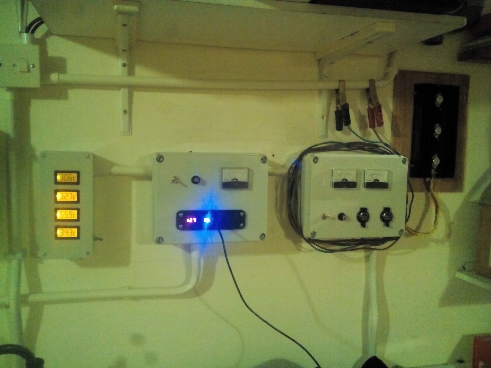
The below are the 50 amp amp digital meters. 
(NOTE - These amp meters require an isolated supply from the current which they are measuring).  


I opted for these 32 amp DC Bussmann fuse holders which I soured from RS Components.

The Power meters which I soured from ebay is displayed below. It's quite cheap when one considers all it's functions.


Thursday, August 17, 2017

Off Grid PV System Upgrade

Finally I found the time to upgrade my off-grid system. As of today it consisted of;
for a total of 1080W STC.

I built a custom frame using 40mm galvanized iron pipe to support the panels.
The structure actually consisted of two parts;
  • One 6 meter long across my roof/property.
  • One 2 meter long across my house water tank.
The 6 meter structure has been installed 1.5 meters high (enough for me to walk under), supported on bricks (filled in with concrete to add more weight) and anchored to the building using chains.

The picture below is showing the new installed panels, photo taken from the side


Picture of the installed panels, photo taken from underneath the panels.


Left sided panels, installed just above the solar water heater panels.


The structure has been installed on filled in brick blocks and anchored to the building.


The new panels have been installed between the grid-tie panels and the 10 year old smaller Sharp Panels installed on poles.


The below is the structure installed on the house roof tank. The roof tank is itself a concrete built tank.


Therefore in total I have installed;
  • 6 x 150W from solartronics for the 24v system for a total of 900W STC.
  • 1 x 150W from solartronics for the 12v system.
Summing up,
12v system = 200W
24v system = 1980W


Tuesday, August 15, 2017

12v System Upgrade

The 12v system has been upgraded. The old system had a too small solar panel and the 12v batteries were very old, always struggling to hold a charge.
It was time to replace the batteries and add more solar power.
1) The batteries have been replaced with a new set of Trojan 6v T-105 Deep-Cycle.
2) An extra panel has also been added to the existing 12v 50W panel. I installed a 12v 150W solar panel from solartronics, giving me a total of 200W STC. 


This increase in charging required me to also upgrade the control equipment. The picture below is showing the new 12v Control panel, and on the left the Xantrex Charge Controller.


The new control panel consists of 2 x 100 Amp Voltage-Current-Power-Energy meters as detailed below.


 and a voltage meter, displaying both the voltage and percentage capacity.
The power meters have been installed, one measuring the charging current while the 2nd meter measuring the load current. Both charge and loads are protected by fuses.


Due to the higher charging current, I installed a Xantrex charge controller to protect against overcharging the Trojan Batteries. Details on the charge controller can be found here


Off-Grid inverter cooling upgrade

I'm current utilizing a PC UPS as my off-grid inverter. The model is BEST FORTRESS UPS 600VA. It produces a clean sine wave and in fact it can power everything (as long as it's within it's power range) including LED lights, halogen lights, fluorescent tubes and even small motors.


It has been in operation for almost 9 years and to be honest I'm really surprised by it's reliability! This UPS was never designed to be in operation/inverter mode for 24/7 with a 50%+ load almost continuously, however it has performed this task for all these years without any hiccups. 
One of the most important upgrades which was required on this UPS to offer all these long years of service was the adding of active cooling. The UPS comes with passive cooling which is just NOT enough!
The cooling system is made up of 6 x 40mm 24v fans. 


I know this from experience, since once the cooling fans stopped working and the UPS went from warm to hot.... in fact the transformer was starting to boil. Thankfully, the protection fuse finally blew, saving the UPS. 

4 fans have been installed on the side (using the existing cooling holes) while another 2 have been installed on top (drilled 2 x 40mm holes), just above the transformer and the power transistors.


The Image below is displaying the power transistors heat-sinks and the power transformer. In between, I placed a thermistor which will record the temperature of both the power transistors heat-sinks and the power transformer.


The image below is displaying the inverter opened without the cover. Instead of the batteries, there is now the fan controlling circuit and a large reservoir capacitor (150,000 uF - 50v). 
The Inverter is taking power from the capacitor which in turn is being fed by 10mm cables. 


The image below is displaying the fan controlling circuit. It's basic function is to switch on the cooling fans when the temperature inside the inverter reaches about 40°C. Details of this circuit can be found here


Inverter cooling circuit


Circuit Description:
The circuit is based around the LM324 quad Opamp configured as differential amplifiers.
QA1a generates a very stable voltage, set to 10v, while QA1b will compare this stable voltage against the voltage difference generated by the thermistor. The thermistor is an NTC 47K. NTC stands for Negative Temperature Coefficient i.e. the resistance decreases when the temperature rises.
Opamp QA1b inverting input (-) is preset to 8v while the non-inverting input (+) is fed from the voltage difference between the 47K preset and the 47K thermistor. When the temperature rises, the thermistor resistance will decrease and therefore the the non-inverting input (+) voltage will rise. Once the non-inverting (+) input is higher than the inverting input (-), the output of the opamp will go high, turning on the transistor Q1 which in turn will turn on the relay RLY1. The relay will in turn switch on the cooling fans.
Capacitors C2, C3, C4 & C6 offer some hysteresis so that the fans will not switch on/off continuously.
U1 is a 7812 voltage regulator. Since the available voltage inside the inverter is 24v and the circuit needs 12v, the regulator is used to step down the voltage, smoothed further by C1.

Parts List:
D1 - 5.6v Zener Diode
D2, D3 - 1N4001
D4 - Red LED
U1 - 7812 voltage regulator
OA1a, OA1b - LM324
R1 - 4.3K
R2 - 5.6K
R3 - 1K
R4 - 5.6K
R5 - 47K Preset
R6 - 1K
R7 - 47K Thermistor (NTC)
R8 - 47K Preset
R9 - 1.2K
C1, C5 - 2200uF
C2, C3, C4, C6 - 1000uF
Q1 - TIP122
RLY1 - Relay

Monday, August 14, 2017

Battery Charger

As part of the house electrical update, I also rebuilt the car battery 12v charger. This has been improved to deliver more current, thus charging the car battery faster.


Circuit Description:
The circuit is built around the voltage regulator U1 - 7812. This regulator has been wired to deliver a higher voltage than 12v, enough to charge a car battery. Output from the regulator is limited to just 1 amp, definately not enough to charge a car battery in a reasonable amount of time. The current has been amplified by using transistors Q1, Q2 and Q3 wired in parallel. The output from the regulator is used as a base voltage/current for the power transistors. Each transistor can carry 4 amp (peaking at 15 amp), thus 12 amp can be easily delivered from this power supply. Obviously, these power transistors will need adequate cooling and therefore I have used a large heatsink. Each Transistor is fed through an 0.1 ohm 9W resistor. This is used to balance the input current. Also, the emitter output from each power transistor is about 30 cm long. This is also used as an emitter resistor to help out in current balancing as well.
BR1 is a 35 amp full wave rectifier. I just needed one diode and opted to use this rectifier since I didn't have a single +20 amp diode readily available.

Parts List:
SW1 - 15amp Toggle switch
F1 - 10amp
C1 - 100nF
C2 - 10uF
C3 - 1000uF
C4, C5, C6 - 4700uF 25v
U1 - 7812 voltage regulator
R1, R2, R3 - 9W 0.1 ohm wire-wound resistors
R4 - 4.7K
R5 - 1K Preset
BR1 - 35amp full rectifier
Q1, Q2, Q3 - 2N3055
Q4 - BC559

This photo below is showing the battery charger connections


The installed battery charger. I opted to install the power transistors outside of the connection box to improve heat dissipation.


Panasonic Base Power Supply

I have setup a Panasonic KX-TG8424EB 4 set cordless telephone system at home. All telephone Bases use a 6v power supply. 
I have managed not to use the chargers on the phones and instead installed 7v solar panels, which is enough to charge the individual phones during the day. Details can be found here.
However, the Base charger needs to be always on since it needs to receive and transmit the telephone conversation. 
I discovered that the Base station cannot use the same 12v supply rail as the router (through which the telephone system is being received). I therefore needed an isolated power supply for the base station.
I found the below DC Converter isolator online. It receives a maximum of 12.6v and outputs (totally isolated) 12v. This device can handle 250mA working at an efficiency of 75%. I opted to parallel two isolators instead of one to get more current output. 


The below circuit basically needs a 12v-24v input from the house batteries and outputs an isolated 7v supply for the base unit. 


Circuit Description:
The circuit is pretty easy and straightforward. The input is limited to 12v using the U1 7812 voltage regulator. During the day when the 12v batteries are charging, the voltage may even go up to 14v enough to burn the isolators so better safe then sorry! The 7812 voltage regulator will always maintain the input voltage to the isolators at 12v.
Output from the isolators is fed to a 7808 voltage regulator where it is further smoothed and fed to the base unit.

Parts List:
D1, D2 - 1N4001
D3 - Green 3mm LED
D4 - Red 3mm LED
U1 - 7812
U2 - 7805
U3, U4 - HDN3-12S12A1. Isolated Power Supply Module 12.6v In / 12v Out, 250mA.
R1 - 1K
R2 - 1.5K
C1 - 4700uF 25V
C2, C3 - 2200uF 16v
C4, C5 - 0.1uF

The pictures below are showing the finished circuit. Notice that both voltage regulators are fitted to a heatsink.


Saturday, August 12, 2017

12v Supply Station


As part of my house electrical installation, I have installed a 12v DC station. Supply is taken from the 12v DC batteries and delivered through a cigarette lighter adapter and 2 x USB Chargers.

I installed the below adapter which contains;
  • A Cigarette lighter
  • 2 x USB outputs
  • Digital voltmeter.

The unit is fused and a 5 amp analogue meter displays has been installed to measure the current consumption.


There isn't much inside the box, just the 3 large smoothing capacitors and all the necessary connections.


The image below is displaying the 12v Supply station installed between the Temperature Monitor (Left) and the Battery Charger (Right).


Temperature Monitoring

Temperature monitoring is critical for the correct function of any electronic system. Once an electronic component heats up, it can either shut down or else short circuit. The latter can result in over current and eventually fire (if no suitable protection has been installed).

I bought the below temperature meters from eBay. They seem to be designed to be installed in computer cases to measure CPU temperature. They come with a couple of meters wire probe length, however this can be very easily extended.


The meters are powered from the 12v battery system, using a 7805 voltage regulator to supply them with a 5v DC supply.


The image below is displaying 4 different temperatures as measured on a August afternoon at about 14:00.


  • The Top display is the room temperature, i.e. in my case, the garage were I have all electronics & batteries installed.
  • The 2nd display is monitoring the temperature inside the shunt box detailed below. Installed are 5 x 50 amp + 2 x 100 amp shunts, together with fuse holders.
  • The 3rd display is monitoring the temperature of the off-grid inverter. Note that the temperature sensor is install on the outside of the inverter. Eventually I'll place it inside and will therefore read a higher temperature.
  • The 4th display is showing the SMA 2KW grid-tie external heatsink temperature.

The image below is displaying the temperature meters as installed together with the other components in the garage.


Capacitor Bank

Since I have a number of DC appliances which are using directly both the 12v & 24v supply rails, it was imperative that I make sure that my DC supplies are as smooth as possible, without any spikes and with the least amount of voltage fluctuations.

A list of appliances which are utilizing directly the DC supply rails can be found here. Loads with motors will generate spikes and back-emf. In my case there is the Reverse Osmosis pump and also In Summer I utilize multiple low voltage pumps to circulate water for the pool.

The below image is displaying the capacitor bank / protection devices installed. 


Actually there are 2 separate circuits, a 12v (top board) and a 24v (bottom board). Both circuits are almost identical except for the components working voltages.
The circuits consist mainly of the following components;
  • Large electrolytic smoothing capacitors. When a huge DC load is switched on, this will starve temporarily the DC lines, i.e. due to a higher current demand, the voltage will go down. These large capacitors will smooth this effect.
  • Smaller electrolytic smoothing capacitors with a low ESR (Equivalent Series Resistance). These capacitor also offer a smooth DC voltage when a huge DC load is switched on. The added benefit of a low ESR is better ripple suspension.
  • Non electrolytic  capacitors. These capacitors offer high frequency suspension on the DC lines. (I have installed 4 Battery Desulphators, 2 per battery bank, and since these work by generating high frequency pulses, I though to be safer if I also compensated for these pulses not to reach my appliances).
  • Multiple voltage varistors. Varistors, also known as voltage dependent resistors work by varying their resistance varies with the voltage. In this case, if the DC voltage for the 12v supply reaches 14v+, the varistor will shunt the supply rail thus preventing the supply rail from reaching excessive voltages. Same for the 24v supply, If the voltage tries to exceed 32v+, the respective varistors will shunt the supply rails.
  • Blocking diodes. These diodes are fitted in reverse order thus they will only conduct and will suppress any back-emfs

Parts List:
  1. C1-C3 --> 100,000uF 63v
  2. C4-C8 --> 470uF 50v Low ESR
  3. C9 - 470nF
  4. C10 - 0.1uF
  5. C11 - C13 --> 100,000uF 25v
  6. C14-C18 --> 470uF 50v Low ESR
  7. C19 - 470nF
  8. C20 - 0.1uF
  9. D1 - Orange LED (24v)
  10. D2 - Yellow LED (12v)
  11. D3, D4 - 7amp Diode
  12. R1 - 1.2K
  13. R2 - 2.2K
  14. VAR1 - VAR5 - 32v Working Voltage Varistors
  15. VAR6 - VAR10 - 14v Working Voltage Varistors