Wednesday, November 9, 2011

Off-Grid System Setup

Off-Grid System
My off-grid systems have been online for the last 5 years, installed in 2006 and basically consists of a primary 24v setup and a secondary 12v setup. My scope for this setup is twofold,
  1. Have a backup system in case of a system outage. Although it will not power and provide all my electricity needs, at least it will handle the basic. 
  2. Reduce my electricity consumption.
Specifications - Primary System (24v):
System DC voltage: 24v
Solar Panels: 4 x 80W Sharp panels, totalling 320W.
Wind turbine: Modified 400W Air-X Marine wind turbine. Details of the modifications can be found in this post.
Batteries: 2 set of 24v fork-lift batteries. Total of 12 batteries per set @ 2v per cell. (about 8 years old when I took them and unfortunately had been heavily abused - sat discharged and lacking electrolyte for a long time and therefore the plates have been exposed to the air and most probably are heavily sulphated). No idea about their current capacity; although I'll measure it and post my findings in a separate post, however they are very, very heavy and each cell physical size is:
  Set 1: 20cm width x 15.5cm depth x 40cm tall
  Set 2: 20cm width x 12cm depth x 46cm tall

Note: These batteries have been changed to a new set. Details can be found here.

Inverter: Modified BEST FORTRESS UPS 600VA. This is basically a computer UPS, with these modifications;
  1. Removed the two internal 7AHr batteries and instead redirected the UPS to get it's power from an external source, i.e. the fork-lift batteries.
  2. Removed the internal beeper which acted as an alarm when the UPS was operating on batteries. Obviously in this case I didn't want the beeper to sound for 24 Hrs a day!
  3. Installed two CPU fans to help in cooling. This UPS relied exclusively on convection for cooling. Since this UPS was going to be used 24Hrs a day and in inverter-mode, it was getting quite warm especially in Summer due to the higher ambient temperatures. I therefore built a circuit to automatically switch on the fans when the UPS internal temperature reached a certain threshold, set to approximately 40°C. The circuit can be found here.
Desulfator: Infinitum 24v battery life optimizer.

Specifications - Secondary System (12v):
System DC voltage: 12v
Solar Panels: Two small panels totalling about 40W
Batteries: 1 set of 200 amp hr ex telecoms batteries.

--> Update! Batteries & Panels have been upgraded/replaced!


Usage:
My house loads are the majority 240v 50Hz AC, however I do have some loads which work directly from the DC batteries.

I've listed below the pros and cons of a DC system versus an AC system.
Advantages:
  1. Running DC loads will eliminate the inverter inefficiencies.
  2. Transformers and/or chargers inefficiencies are also eliminated (or reduced).
  3. The inverter can be lower rated since it won't need to handle all the house power.
Disadvantages:
  1. DC appliances may be more expensive to purchase.
  2. DC appliance may be more difficult to source especially from local suppliers.
  3. A separate DC wiring infrastructure is needed.
  4. Since DC wiring is low voltage, compensation for voltage looses will have to be made up using extra thick wiring.
DC loads
Having said all this I still opt for DC loads when possible. Although my DC load is limited, it currently consists of;
  1. Several 12v DC LED lamps (installed in the kitchen).
  2. Several 12v DC halogen lamps (installed in the kitchen cupboard).
  3. 15'' Digital picture frame.
  4. Cable modem (TV, Telephone and Internet).
  5. WIFI router 
  6. Reverse Osmosis pump
  7. Well-pump automatic relay circuit.
  8. House alarm DC supply.
  9. Weather station - step-down to 6v.
  10. Walk-in wardrobe lighting.
  11. Chimney space heating.
  12. Electric Shoe Dryer.
  13. Wardrobes Internal LED lighting. These are enabled automatically on opening the wardrobe doors.
  14. Panasonic Cordless Base Station
 AC Loads
Currently the inverter powers;
  1. All the house lighting.
  2. TV, DVD, decoder, Hi-Fi.
  3. Solar water heater circulating pump.
  4. Multiple 13amp socket outlets distributed across the house.
 -----------------------------------------------------------------------------------------------------------------------

Below I have attached  pictures of my system.

24v battery sets. Both sets are enclosed in wooden boxes to disable access to my two small children to the battery terminals! Batteries are located in the garage so no problems with regards to heavy gassing.


The 4 Sharp solar panels configured in series/parallel. Each set is installed on it's own pole and feeds its own on/off switch,fuse & amp meter (as shown further down on the DC monitor box). I'm running a common negative 20mm wire for the panels while using a 4mm wire for each set of panels.


General view of my garage wall. Several components are being displayed, listed below;


1) The yellow box is the SMA grid-tie inverter.

2) Below the SMA inverter is the main change-over switch which is used to switch over the house lighting circuit from either the inverter or the local utility provider. The three meters on the same box are a frequency meter, an AC voltmeter and an AC amp meter.


3) The box left of the SMA inverter is a DC junction box with 300 amp switches. 1 red switch is used for the inverter, while the other red switch is a two position switch connected to both 24v battery sets.


4) The 600VA inverter is located on a small shelf (top right hand corner)

    5) Below the 600VA inverter are the wind turbine electronics.

      6) Next to the wind turbine electronics box is located a 24v DC meter box (details just below).
      7) The small box located at the very bottom is the 12v DC meter box (details further down below).

      Below is photo of the several DC meters which I use to monitor the system.

      1. On the left are four DC amp meters, feed from the solar panels.
      2. The right-most meter is an amp meter fsd 10amps used to monitor charging from the wind turbine.
      3. The middle top meter is a 30v fsd meter
      4. The middle centre meter is a 30 amp meter. It measures the total charging current (Solar + Wind + Charger)
      5. The middle bottom meter is another 30 amp meter measuring current consumed (Inverter + 12v Chargers + DC appliances)
      The picture below is displaying the 12v DC meters.


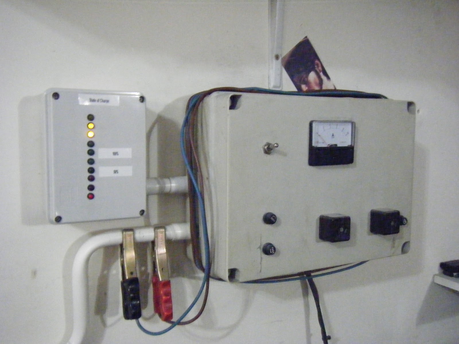
      The box above serves three purposes.
      1. Monitor 12v system. The left meter is a 5 amp meter measuring the 12v DC load. The right meter is another 5 amp meter measuring the 12v DC charging current. (Solar Panels + Wind Turbine + automatic charger)
      2. Controls the 12v system.The bottom left switch and fuse control the Power out. The bottom right switch and fuse control the Power in.
      3. 12v automatic charger. The internal charger monitors the 12v batteries and if the voltage falls below a certain threshold (currently set to 12.4v), the charger automatically kicks in down-converting power from the 24v system. The charger remain on for 5 mins (irrespective if the voltage went up), after which it switches off. If the battery voltage is still low, the charger will switch on again, repeating until the battery voltage is above the threshold. The centre LED indicates when the charger is ON. The charger is based on the popular 7812 (1 amp) fixed voltage regulator, having it's current output increased to 8A thanks to two 2N3055 transistors, mounted on top to help dissipate heat. The heat sinks are clearly visible...


      The below two boxes are;

      The left box is an LED voltmeter for the 24v system used to indicate the State of charge (SOC).


      The right box is a 12v battery charger, taking it's power from the 24v system. The charger is based on the popular 7812 (1 amp) fixed voltage regulator, having it's current output increased to 8A thanks to two 2N3055 transistors mounted inside the box. This charger is mainly used to charge any 12v batteries such as our cars starting batteries.

      The below photo is showing a 24v charger. Nothing fancy about it. Just a transformer, two 35amp bridge rectifiers in parallel mounted on a heat sink and a large electrolytic capacitor to smooth out the output. This charger is only used in emergencies, i.e. when the batteries SOC goes down below 50% and no charge from the solar panels is available.


      Thursday, November 3, 2011

      Air-X new controller

      I have removed the internal Air-X circuit board from the turbine nacelle as described here and instead built three simple circuits to convert and connect my 24v Air-X marine turbine to the batteries.

      I've called the circuits;
      1. Rectifier Circuit
      2. Brake Circuit
      3. Controller Circuit.

      1. Rectifier Circuit
      Below is the main three-phase rectifier circuit. B1, B2 and B3 are 35 amps 200v rated bridge rectifiers. I've used three separate bridge rectifiers instead of one three-phase rectifier simply because it was easier to source and it turned out to be cheaper too. The three phases from the turbine is fed into the three rectifiers producing a wild varying DC voltage. This output is connected to either the 12 or 24 battery sets through a relay as described below in the Controller Circuit.

      2. Brake Circuit
      The braking system I opted for my wind turbine is a manual system.
      The original Air-X used it's internal controller to electronically brake the turbine. This used to happen by applying a brute short circuit across the phases without first slowing the turbine down. This sudden braking used to violently shake the turbine, transmitting the vibrations down the turbine tower, adding unnecessary  stresses on the turbine blades and thus increasing the possibility of blade fractures!
      I decided to improve the braking system by stopping the turbine in two stages. First a load is applied across the three phase, slowing down the turbine and approximately 10 seconds afterwards, the three phases are shorted out.

      With reference to the below circuit, switch S1 is the braking switch. When it's closed, i.e. the brake applied, two things will happen;
      1) Relay RL1 is immediately energised and the three phases are shorted out through resistors R3, R4 and R5. These resistors are 1Ω 100W resistors mounted a heat sink. This will slow down the turbine.  
      2) The 'delay circuit' kicks in. Capacitor C1 starts charging through diode D1 and resistor R1. When it reaches a certain voltage (thus the delay), transistor TR1 is switched on and this in turn will energise relay RL2. Relay RL2 will short out the turbine three phases, thus applying the maximum load which will stall the turbine. Diode D3 will protect TR1 from RL2 back emf. The delay can be increased by increasing R1 and/or C1.
       
      3. Controller Circuit
      The below circuit is the new controller I've built for my Air-X. It's much simpler than the original internal regulator, however I now have the added benefit of charging 12v batteries in low wind conditions.


      The three phase from the turbine is rectified by two bridge rectifiers B1 and B2. These are 1 amp rated rectifiers and their output is used to;
      1) Power the circuit itself, including the controlling relay. No external supply is needed to power the controller. I will just use 0 watts in no wind conditions.
      2) Used as a reference voltage to control the controller (relay) output.
      Capacitors C1 and C2 provide smoothing to the rectifiers output, while LED D2 acts as a quick reference to indicate the current turbine power strength. The higher the turbine spins, the brighter the LED.
      The varying DC voltage is fed to a 12v voltage regulator IC1 and it's output is further smoothed by these large capacitors; C3, C4, C5 and C6. These capacitors act as reservoirs to power the circuit. They are needed to reduce any voltage fluctuations due to fast changing wind conditions. 
      IC2 is the popular quad opamp LM324. In this case, I'm using only one of the opamps in a comparator mode.
      Pin 2 is held fixed at 6v (half the regulated supply voltage) by the voltage divider resistors R5 and R6. Capacitor C8 helps in keeping this reference voltage constant.
      On the other hand, Pin 3 is fed from the turbine unregulated output through potentiometer P1, R7 and D5. This varying voltage is smoothed by capacitor C9 which also act as a reservoir to eliminate any fast-changing wind conditions.
      When pin 3 is lower than pin 2, i.e. in low wind conditions, the output from the opamp is off, TR1 is off and relay RL1 is De-energised and therefore the output from the turbine connected to the 12v batteries.
      When pin 3 goes higher than pin 2, i.e. in high wind conditions, the output from the opamp is on, TR1 is on and relay RL1 is energised and therefore the output from the turbine connected to the 24v batteries.
      Potentiometer P1 is used to adjust the threshold voltage at which the turbine is connected to either the 12v or 24v batteries.
      LEDs D3 and D4 indicate whether the turbine is charging the 12v or 24v battery sets. D3 is on when the opamp is on i.e. in the 24v mode while the green LED is on when charging the 12v batteries.

      Completed circuits
      The three above circuits have all been housed into a plastic box as shown below.


      • Attached to the top heat sink are the three bridge 35 amp rectifiers.
      • Attached to the right heat sink are the three 1Ω 100W resistors used for the first stage of the brake system.
      • The three relays in the middle
        • The left relay controls the output from the controller, i.e. charging either 12v or 24v.
        • The middle relay is the dead-short across the turbine output. Full break.
        • The right relay is the brake first stage relay which shorts the turbine output across the power resistors, slowing it down.
      • The controller circuit is sitting at the bottom of the box.

      Thursday, October 13, 2011

      Home Energy Audit

      It all started from an article which was published on the TimesOfMalta website of the 12th June 2011. The article made reference to an energy competition, the European Citizens Climate cup. I joined, and being one of the first 50 participants to register, I was awarded a free energy audit from Projects in Motion Ltd.

      On the 4th of October 2011, Ing Kevin Alamango visited my house and performed the energy audit of my property. Me and my family (well we all have to pull the same rope) are satisfied with the results, obviously there is still more work to do. I would really like to thank Kevin for his time and professionalism. The audit results can be found here

      Thursday, September 15, 2011

      Product Review - Tecco Solar Air Conditioner

      Last July, I've installed a Tecco Solar Air Conditioner in my living area and I've decided to write a small review to better evaluate it's performance and eventually help others determine if this is the right AC unit for them.


      Product Details.
      The product details below have been copied over from Teeco's specification sheet...

      Company: Teeco Group
      Website: http://www.teccogroup.com/tecco/
      AC Type: Teeco Solar Assisted AC
      Model: TACW-60 (20,000btu Cooling, 22,000btu Heating)
      EER: 3.88 W/W or 13.24 btu/h/W
      Cooling Power Input: 1350W~1560W / 6.14A~7.09A
      Price Paid (Including installation): Euro 1050

       I did my own measurements using both a digital clamp meter and a watt hour meter, using the 'Energenie Appliance Power Meter'.

      Conditions:
      Area of the room: 28 m2
      Volume of room: 84 m3
      Voltage: 230.1v AC 50HZ
      Duration of observations: 1 hour (17:30 --> 18:30) - Sun was almost down and therefore the AC Solar collector was not being heated by the sun during the test duration.
      Temperature thermostat setting: 16°C (Didn't want the compressor to switch off/on during the test!)

      Starting room temperature: 28.1°C
      Temperature (outside monitored room): 30.9°C
      Heat Index (outside monitored room): 34.3°C

      Results:
      Power Factor: 0.93
      Cooling Power Input: Ranged between 1420W ~ 1550W.
      Maximum Power (Compressor switching on): 1700W.
      Standby Power consumption: 1.7W
      Cumulative power consumed: 1.1KWh
      Carbon Dioxide generated: 0.9Kg

      Final Room temperature: 24.4°C
      Temperature (outside monitored room): 29.7°C
      Heat Index (outside monitored room): 32.5°C
      Temperature Room Difference: 3.7°C

      Conclusion:
      Looking at the results, I can conclude that specifications are pretty accurate and reflect the actual unit performance.

      Friday, September 9, 2011

      2KW Grid-Tie system setup

      Hello

      This post marks my almost 2000 KWH produced so far and sold to Enemalta (my local power provider).

      My Grid-Tie system basically consists of:
      1. 9 (nine) 230W solar panels. IBC PolySol 230TE
      2. One SMA Inverter. Sunny Boy SB 2100TL Transformerless solar inverter.

      All items were bought from a local company - Crosscraft Energy which specialises in renewable energies and energy saving products. I must say that I'm truly happy with their service, expertise and after sales service. C

      I've attached some photos below to demostrate my setup.
      The above photo shows the nine 230W panels. Showing also in the background are another 4 smaller panels, (mounted on poles at the back) used for the off-grid system and also one of the water solar collectors (right panel).


      The above photo shows three of the panels aluminium structure (as supplied by Crosscraft), bolted to eight concrete filled-in bricks acting as anchors.


      Another photo from above.


      The above photo shows the bottom string of panels mounted at 30 degrees to the building. A special galvanised structure was built to accommodate these panels. Special thanks go to my neighbour Mario for helping me with the structure, both building and mounting.


      The above photo shows the SMA 2100 inverter. Note that contrary to many installations, I mounted the inverter in the garage (ground floor).
      My reasoning was simple;
      1. Inverter is NOT exposed to weather elements such as rain, sun, heat and salt (I'm located close to the sea).
      2. My garage indoor temperature is much lower than the temperature beneath the panels where the inverters are normally mounted. This will provide my inverter with a more comfortable temperature to work in. Lower temperature  = prolonged service life, this being applicable to any electronic component!
      3. If needed, I can add extra cooling to the inverter by placing fans, something not possible and practical if the inverter is placed outside.
      4. By tapping on the inverter, the display comes on and I can know at a glance how much energy I produced, being today and/or cumulatively. If the inverter was mounted on the roof and underneath the panels, accessing it would prove to be more difficult.
      5. Less losses contrary to what most believe! My panels are all connected in series, totalling 264v DC (STC 29.4v per panel x 9). This is higher then the 230v-240v AC rms if the inverter was located on the roof. The higher the voltage, the less the power loss. Besides, I used extra thick cables to compensate for any voltage drop. Normally 4mm is used however I went for a 10mm cable run. This reduces the voltage drop by half when compared to the 4mm.

      The above photo shows a section of my garage wall were I have my controls mounted. The yellow box is the Grid-Tie inverter.

      I'll be posting my production statistics in a seperate post.

      Friday, August 26, 2011

      Air-X Modification

      My Air-X stopped working during a winter storm, wind > Force 9+ sometime in February 2011.
      After taking the turbine down for inspection, I found out that both the circuit board and air-x stator where fried. This was my third time that the circuit board failed (in 5 years) and the first time the stator got fried. I sent for quotes to replace the burnt parts, however thinking about it, I decided that I will not replace the circuit board again. Being the third circuit board replacement was enough for me. I find it really stupid to put electronics high up in the nacelle where maintenance and replacements become a nightmare because of the trouble to lower the turbine. Having some background in electronics, I decided to built a simpler circuit myself, advantages being:
      1) Less complex
      2) Since I have designed it, it will be fairly easy to diagnose & repair in case of failure.
      3) I'll install it somewhere practical instead of in the nacelle 40 + feet up!
      4) I'll improve the turbine charging characteristics. My Air-X is a 24v model and it needs quite a bit of wind to start charging my 24v batteries. Having also a separate 12v system, I decided to built a circuit to charge both my 12v and 24v batteries, the circuit itself switching battery banks automatically depending on the turbine output.
      In this way I will gain some power when the turbine is spinning enough to charge the 12v battery bank BUT not enough to charge the 24v battery bank.

      Before starting working on the circuit, I needed to modify the AIR-X yaw assembly. Three wires come out of the AIR-X, Positive, Negative and Earth (this being also earthed to the nacelle body). Moving the circuit controller away from the nacelle will require the three wild AC phases to be redirected down the tower. I could successfully use both the Positive and Negative wires for two of the phases however I could not use the Earth connection for the third phase since this connection was also connected to the nacelle body, which is eventually also earthed as part of the tower. Besides this problem, the yaw brushes were mounted on the circuit board and therefore I needed a new brush holder assembly.

      My neighbour Mario came to the rescue. Being a professional machinist, he modified the yaw assembly (as detailed below) to isolate the bottom Earth connection from the nacelle by adding an extra nylon spacer (white). Please note below the three isolated rings against which the brushes will make contact.


      As illustrated below, a new brush holding assembly has been designed and built. The three wild AC phases are connected to each brush and these brushes make contact with the yaw assembly which will transfer the three phase down the tower.


      The diagram below shows the fully assembled new AIR-X turbine.


      Once the turbine mechanical work was done, I built the new circuit board as displayed below. I'll be posting the circuit diagram and describing how it works in a future post. The circuits are detailed here

      The circuit board has been installed in a more practical location, in my garage next to my other equipment!