Scope
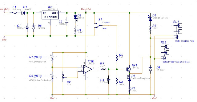
The scope of this circuit is to use my existing Steca TR0301 differential controller, but connected to two heat sources (log fireplace and solar collector) and two circulating pumps. The simple circuit below will enable me to continue using the TR0301 controller while at the same time reading temperature from two heat sources and controlling two independent circulating heat pumps. The storage tank is the common factor.
Background
In Malta, the log fireplace is only switched on for a maximum of three months (at least in my case) and therefore I couldn’t justify purchasing another differential controller just to be used for only three months. Also, I do not light the fireplace during the day when the solar collector is working. In fact the solution I’ll be explaining can only have one heat source active at a time.The circuit has been built to be reliable using the least number of electronic components. Since the majority of the time the controller will be controlling heat from the solar controller, the circuit has been designed to be ‘off’ the majority of the time, i.e. the relays de-energised.
Circuit Description
The circuit is powered from the house 24v DC supply. This is stepped down using IC1 7812 linear voltage regulator. IC1 is fed via fuse F1 and diodes D1and D6 protect the circuit in case of a polarity reversal. Capacitors C1 and C2 provide supply smoothing while the green LED D2 indicates that the 12v supply is available.
The circuit is based on the quad opamp LM324. In this application I’ll be using only one of the four opamps. Pin 6 (Inverting input) is pre-set to approximately half the supply voltage *, while Pin 5 (non-inverting input) is set by thermistors R6 and R7. These thermistors are identical 47K NTC type located at the solar collector and the other attached to the chimney pipe. NTC thermistors reduce resistance once the temperature is raised.
Two scenarios are available;
1)
R6 > R7 i.e. Solar Collector warmer than Fireplace.
When the solar collector is warmer than the fireplace, the resistance of R6 will be less than R7 and therefore Pin 5 is taken to Ground. Assuming Pin 6 set to 6v (half the supply voltage), and therefore Pin 6 voltage is higher than Pin 5, the opamp output will be low. Transistor TR1 is OFF and both relays OFF. While OFF,
·
RL1 will be connecting the differential
controller to the solar circulating pump
·
RL2 will be connecting the differential controller to the Steca PT1000 temperature
sensor located at the solar collector
2)
R7 > R6 i.e. Fireplace warmer than Solar Collector.
When the fireplace is warmer than the solar collector, the resistance of R7 will be less than R6 and therefore Pin 5 is taken high to the supply voltage. Assuming Pin 6 is set to 6v (half the supply voltage), Pin 5 voltage is higher than Pin 6; the opamp output will be high. Transistor TR1 is ON and both relays are ON.
·
RL1 will be connecting the differential
controller to the fireplace circulating pump
·
RL2 will be connecting the differential
controller to the Steca PT1000 temperature sensor located at the fireplace
chimney.

No comments:
Post a Comment