Wednesday, July 19, 2017

Fire Prevention

If you go through my blog, you'll find out that I have all the house batteries and almost all power electronics installed in my garage (which is physically linked to my house).


The photo above is showing part of my setup. 
  • Burglar Alarm (12v sealed battery inside)
  • 4 x 12 MCB boxes. 240v AC House circuits.
  • 2KW SMA Inverter (Yellow Box)
  • House Power selector switch and meters with surge protectors inside
  • 12v Control Box with a xantrex charge controller c35. All Fused
  • 24v Control Box. All Fused
  • Battery and Inverter Switches
  • Off-Grid Inverter
  • 2 x 500W Grid-tie Inverters
  • 12v Car Battery Charger
  • Battery Box (12 x 2v Forklift Batteries + 2 x 6v Trojan Batteries)
All of the above can catch fire!
Everything is fully fused as it should be and all wires are properly sized to carry the estimated current, however this does not mean that accidents cannot occur... an electronic component malfunctions and the fuse does not blow or blows late after a copper wire catches fire.

To put my mind at rest I installed two fire extinguishers in the garage.
  1. 6kg Dry Powder extinguisher
  2. 5kg CO2 extinguisher
Both can be safely be used on electricity although I'll prefer the CO2. Having said that in large open spaces, the CO2 may not be enough to extinguish the fire and that's why complimenting with a dry powder extinguisher is a good idea.   


Above - 6kg Dry powder


Above - 5Kg CO2


Tuesday, July 18, 2017

Battery Desulfators

Basic technical information.
Basically, lead acid batteries are made up of lead and lead dioxide plates immersed in an electrolyte or sulfuric acid.
During normal use the sulfuric acid reacts with the lead dioxides plates to generate electricity (i.e. power) and in the process a thin layer of solid lead sulfate crystals are deposited on the plates. If inspected, these crystals will cover the battery plates and looks white as shown below.


This hardened lead sulfate is an unwanted product of this chemical reaction and is called sulfation, one of the main reasons why lead acid batteries start loosing capacity and eventually become unable to hold any charge and need to be thrown away. This happens because these large crystals clog the pores of the lead dioxide active material and therefore charging becomes impossible.
During charging, the reverse process occurs and the lead sulfate is converted back to lead dioxide and sulfuric acid, restoring the battery to it's pre-discharge state. Unfortunately, this charging process is not perfect and in fact with every charging/discharging cycle, more sulfate is deposited on the plates and never removed, thus the battery loosing slowly it's original capacity. That's why a battery is also rated on the number of cycles it can sustain. A cycle is considered to be a battery from a charged state, discharged and charged again. Expensive fork lift batteries are rated to sustain > 3000 cycles i.e. if the battery is charged/discharged daily, the battery can survive 8+ years with very little loss of capacity!
A battery desulfator is a device which will clean the batteries internal plates, i.e. it's able to remove the hardened crystals (which were not previously removed by the normal charging process) and restore the battery to a better state, holding more charge and capacity. A good desulfator uses pulse frequency to dissolve these crystals.

There is a lot of literature and videos on the internet about Battery Desulfators however all seem to lack to draw a definite conclusion, do Battery Desulfators really work?

Deep Cycle Batteries are expensive! In fact I preferred to spend extra Euros on the Desulfators in the hope that they will maintain my batteries in better shape and prolong their useful life.

Installation
I opted for these Battery Desulfators from infinitumstore. I like their design, fully enclosed/sealed making them ideal to sit next to batteries. Also these devices use Amplitude Modulated Pulses at the resonance frequency of the crystals to shatter the covalent bonds that hold it together.

I installed 4 desulfators in total, 2 in parallel for the 24v forklift batteries while another 2 desulfators in parallel for the Trojan 12v system.

The image below is showing the installation details.

  • The top 2 desulfators are 12v
  • They are installed just after the 12v battery main switch. I used an old (but unused) 240v AC 45 amp fuse box, containing a 30 and 15 amp fuse inside. I used the 30 amp as the 12v battery main fuse, while the 15 amp fuse holder for the 12v desulfators. I did replace the desulfators 15 amp fuse wire with a 5 amp fuse wire.
  • The bottom 2 desulfators are 24v
  • They are also installed just after the 24v battery main switch. I used an old (but unused) 240v AC 60 amp fuse box, containing two 30 and one 15 amp fuse inside. I paralleled the 30 amp fuses as the 24v battery main fuse, while the 15 amp fuse holder for the 24v desulfators. I also did replace the desulfators 15 amp fuse wire with a 5 amp fuse wire.
  • All components have been fitted to a piece of wood which in turn was fitted against the battery box.


The desulfators have been installed just against the outside of the battery box.


Monday, July 10, 2017

Heatsink Water cooled


Introduction
On upgrading my off-grid 24v system, I added more Photo-Voltaic Panels - 900W in total (150w x 6). I decided to sell this all this power instead of storing it into the batteries. I purchased two small grid-tie inverters - 500W peak  each and connected them to the solar panels and grid. They worked well however I noticed that the inverters were getting pretty warm! The inverters are installed in the garage which is South facing. Therefore the garage is exposed to long periods of direct sunlight, raising the room temperature significantly. I measured the temperature in the afternoon and the mercury hit 35 °C. This was forcing the inverters fan to run continuously besides that the inverters were still getting pretty warm.
I needed to find a way to keep the inverters cooler. One way to do this was to water cool them!
This required a lot of preparation because I needed to have a cold water supply next to the inverters, something which was not readily available.  The water cooling supply has been taken from the roof tank (2 stores higher) and thanks to gravity, I did not need a circulation pump to get the water circulating the inverters. The water after passing through the inverter heat-sinks is then dumped back in the well, thus there is no water wastage. The house water well pump would then switch on occasionally automatically (depending on the roof tank water level) and new cold water is pumped from the well to the tank.
I have this system running for the past month now and must say that I'm really satisfied with it's performance. The main objective has been reached in that the inverters are now running much cooler. A cooler inverter (electronics) will translate to a longer working life. The water is being circulated against the heatsink for most of the day but that's OK as long as the inverters are kept cool.

Built Details
The Inverters have been mounted on a 4mm aluminium sheet. A large heatsink has also been fitted to the back of the aluminium sheet to add in thermal mass. Thermal paste has been used to facilitate heat transfer between the two metals.
Two CPU water cooling blocks (as shown below) have been fitted to the 4mm aluminium sheet to allow cold water to circulate and cool the heatsink/inverters.

One Thermal switch has been fitted to the heat-sink. I have chosen a switch which will operate at 35 °C and reset at 20 °C. Therefore once the heatsink temperature reaches 35 °C , the thermal switch will turn on... switching on the water circulation solenoid.


The picture below is showing the underneath of the inverters heatsink. In the middle, I have attached the heatsink, on the left top corner, I have attached the thermal switch while CPU cooling blocks are the blue blocks attached to either side of the heatsink.


Water flow is controller using a 24v AC solenoid valve. A small transformer has been fitted to power the solenoid since it runs on AC! 
An AC solenoid runs cooler than a DC solenoid and that's why it has been chosen.


The picture below is showing the front of the aluminium sheet with the grid-tie power inverters installed.


The picture below is showing the inverters installed to the wall. On the left there is a consumer box with 2 separate double pole MCBs and a KW power meter to measure the amount of power generated by these inverters.
On the left of the inverters, there are the water connections, water feed and return showing also the solenoid box at the extreme right.


The solenoid box installed. A relay has been used to power the transformer which in turn will power the solenoid valve.


Therefore in summary;
The heatsink will warm up. On reaching 35 °C, the thermal switch will close and this will activate the 12v relay coil. The relay contacts will close and this will activate the 24v AC solenoid valve, opening the water flow.


Trojan 6v T-105 Deep-Cycle Flooded

The 12v system batteries have been replaced with 2 x 6v Trojan Batteries rated 225 Amp-Hours at the 20-HR Rate. Details about these batteries can be found on the Trojan website or here 

The batteries have been installed in the battery box to 
1) Eliminate any accidental contact with the terminals. A short circuit on the terminals can easily promote a fire. If a metal object drops on the terminals, a huge current will pass through it. In a matter of seconds the metal object will get so hot that it would be impossible to remove, it may even weld itself to the terminal blocks. This huge current will cause a huge sudden discharge during which the batteries will get hot and may explode.
2) Deep cycle batteries tend to gas heavily during charging. This gas is highly explosive and a spark can easily ignite the gas causing the batteries to explode. The battery box which I have installed is well vented so this possibility is further reduced.


These batteries will be charged using 2 panels.
thus a maximum of 17 amps charging can be reached during the day. A Schneider Xantrex C35 Charge Controller has been installed in 'Diversion Mode' to protect the batteries from overcharging.

Friday, December 11, 2015

Paris has become Greener.

Last week I was in Paris for a short holiday and on arriving at the airport, the first taxi which I took was a hybrid. At first I thought that it was a coincidence, but then I started noticing that a good percentage of the Paris taxi fleet were actually hybrids ranging from PeugeotRenault, Citroën to Toyota.

I also noticed that a number of EV charging points have been installed across Paris since my last visit there 2 years ago, with EVs parked and charging. I found out that Paris has introduced an electric car sharing program and through my experience and judging by the EVs which I saw in the streets, I can say that it's being used quite a lot.

In the past 2 years a lot has changed in Paris and now it has become more Green!


Since I happened to be in Paris in December 2015, when the 2015 United Nations Climate Change Conference talks were being held, I was lucky enough to see a large display of Photo-voltaic panels installed in Champs Elysees serving as a demo to the public on the use of the sun to generate electricity.


I also saw a number of new Hyundai ix35 Hydrogen fueled cars (to be used as Taxis) just in front of the Eiffel Tower. Some more details on this initiative can be found here.


Friday, August 28, 2015

13 Amp 2 Gang Double Switched Socket c/w USB

Product Review - 13 Amp 2 Gang Double Switched Socket c/w USB


I bought a couple of these 13 Amp 2 Gang Double Switched Socket c/w USB from TLC Direct some time ago.


I have tried charging mobiles, wireless headphones, tablets and mp3 players with success! These devices do work well. Since the output is limited to 2.1amps, it means that only 1 amp is available per USB port. That's fine for mobiles, headphones and mp3 players however the tablets will take longer to charge due to the smaller charging current.

These Sockets are really cool. You won't be wasting a 13amp outlet for a charger anymore!

Monday, August 3, 2015

The Electric vehicle arrived!

Finally the much awaited Electric vehicle (EV) Arrived. I Obviously went for the Mitsubishi iMiev which I bought from Mitsubishi Motors.
Having thoroughly tested the car for 8 weeks last year as part of  an EU Demo program, funded by the EU, (Demonstration of the Feasibility of Electric Vehicles towards Climate Change Mitigation) Project no. LIFE10/ENV/MT/088), it was the natural electric car for me to buy.

I had blogged about my 8 week experience here.

I have also linked to the Mitsubishi Motors website for a list of the car's features and characteristics.

The EV has been in service for almost a month now and I have started gathering some real-life data here.

Friday, July 17, 2015

EV Charging


To better monitor my EV charging times/electricity consumption, I installed a separate 13amp circuit distribution box in the garage next to the other distribution boxes.
The circuit consists of two (inside) 13amp socket outlets and an external waterproof dual 13amp socket outlet, installed just outside the main door.
All socket outlets are protected by a separate 30ma ERCB (Salvavita) and a 16amp dual MCB. I have also installed a KWH meter to monitor the EV charging requirements and thus be in a better position to calculate the EV running costs.
The EV circuits will be switched OFF when not in use (as indicated by the Orange Neon indicator).

The image below is displaying four of the distribution boxes.
1) Top Left is all dedicated to the house air conditioning circuits.
2) Bottom Left is dedicated to the House 'general' circuits. Main MCB, ERCB, ERCB bypass etc.
3) Top Right is the new distribution box for the EV charging circuits
4) Bottom Right is dedicated to the off-grid Inverter circuit, consisting of a main MCB, ERCB and a KWH meter.


The image below is displaying the EV charging distribution Box. From left to right are the 30ma ERCB, KWH meter and the 16amp MCB. Then there is also a small miniature switch which will be used to illuminate an LED strip outside the house to mark/indicate the cable crossing across the pavement.


The image below is displaying one of the 13amp socket outlets installed inside the garage, clearly indicating that the socket is to be used solely for the EV charging. It is extremely important that the EV sockets are solely used for the EV charging otherwise they will distort the EV charging requirements!


The image below is displaying the external 13amp socket outlet to be used solely for EV charging


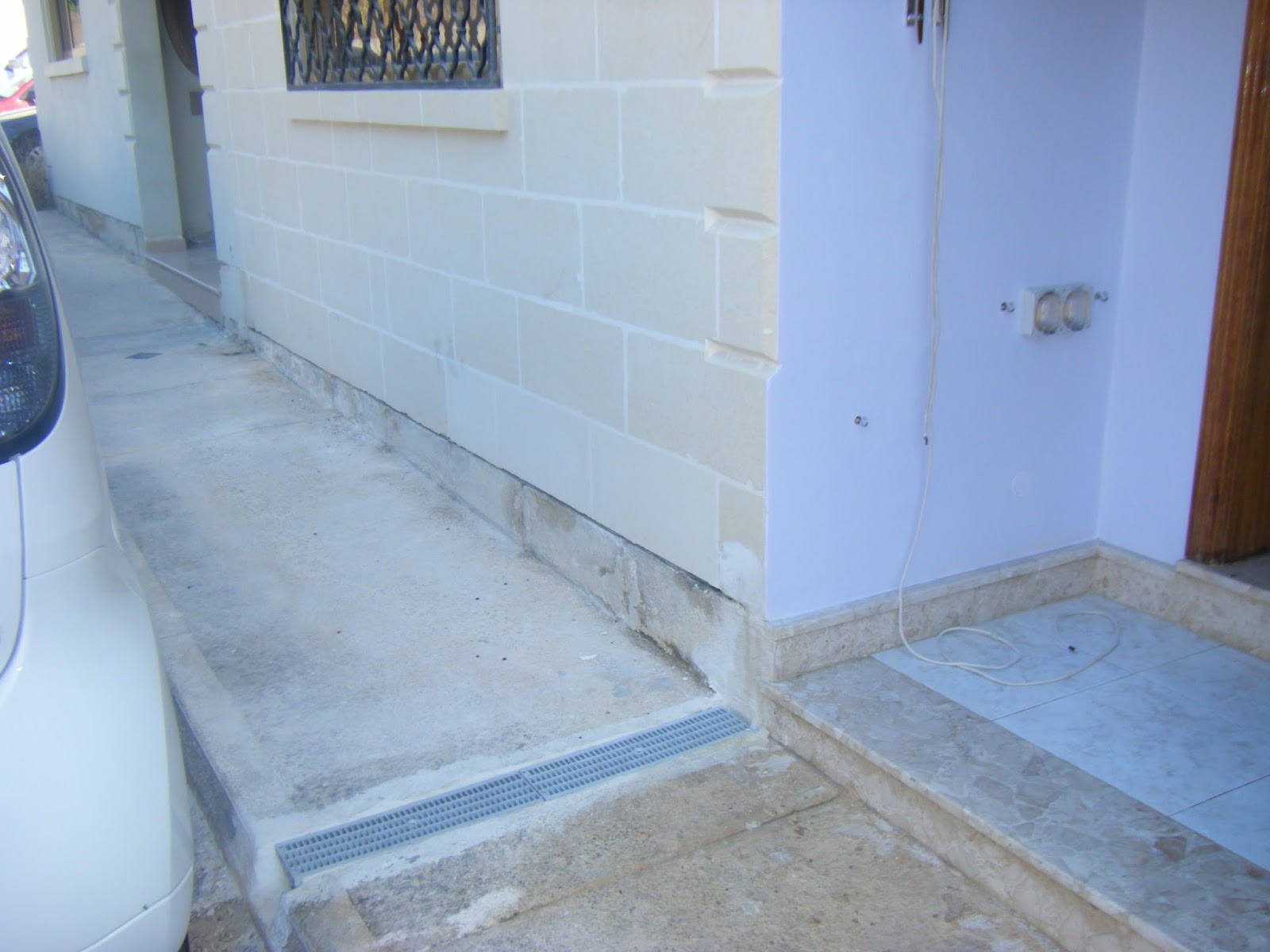
I dug a culvert right outside my property which will be used to pass the charging cable through. In this way there will be no wires running around on the pavement and therefore less chance of people toppling over it!
I'll place/remove the cable each time I need to charge the EV and therefore the cable is only placed temporarily while the EV is being charged.


And here I'm charging the EV at night. Notice how the cable (black) is passing through the culvert.


I have also illuminated the culvert (using a water-proof LED strip) to indicate to anyone passing through that the EV is being charged. Although the EV charging socket is illuminated, I decided that I'll better illuminate the area a bit more so people will notice that a socket/cable are coming out from the EV.


Thursday, May 7, 2015

Swimming Pool Solar Heating


I have installed a small (approx. 4000 litres) inflatable pool for my boys in the yard which is used in the Summer months i.e. between June and September.
The pool is exposed to direct sunlight during the morning/early afternoon hours, approx. from 09:00 till 14:00. This would be enough to heat the pool water, however in Summer I cover the yard (and therefore the pool) with shades to reduce the heat inside my house. The problem with shading is that the pool doesn't get heated well anymore and the water can get quite cold, enough for my boys to start feeling cold.
I used to replace some of the pool water on a daily basis by dumping some of the pool water in the grey water tank and replacing it with warm water from the solar water heater, however this year I have a better solution.
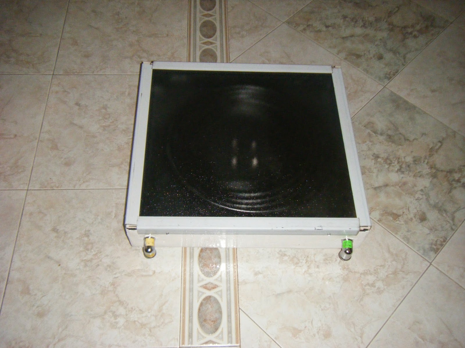
I build a small flat plate collector (50cm x 54cm) with a 15 metre 1/2 inch copper pipe inside the collector, all painted matt black. Then I've covered the box with non reflective glass. The theory behind is that I'll be looping the water from the pool through the solar collector, the water gets heated in the process (it will absorb the heat from the collector) and is then dumped back in the pool. The collector is a small one and therefore the pool water can never reach a temperature high enough to scald the boys, however it should be enough to warm the pool water to a more comfortable temperature.
The size of the collector was something which I had little control over simple because it has to be installed in a tight/small space. In theory, at any moment, the sun emits about 3.86 x 1026 watts of energy. Most of that energy goes off into space, but about 1.74 x 10¹⁷ watts strikes the earth. (ie: 174,000,000,000,000,000, or 174 quadrillion watts). 
If there are no clouds, then 1 square meter of the earth will receive about one kilowatt of that energy.

The image below is showing the underneath of the solar collector box. I have painted it in gloss white and it will be positioned on a 40mm steel pipe.


Below is an image of the inside of the solar box, painted matt black.


Below is an image of the inside of the solar box, with the 15m copper pipe placed and painted/sprayed matt black as well.
 
 
And below the ready solar collector with the glass installed.


I'll be installing the finished collector and water pool soon. I'll be posting some performance data once it's up and running.
 

Monday, May 4, 2015

Central Inverter vs. Micro-Inverter

Central Inverter vs. Micro-Inverter

I'm writing this post because some time ago a relative of mine requested a quote from a local RE supplier and this company recommended that he should install the panels using micro-inverters. The supplier remarked that 'this is the new way of installing panels.' WHAT? True, the technology may be newer than central inverters but that doesn't mean that the central inverters installation is a thing of the past or that micro-inverters are better than central inverters. Both installation types have their pluses and minuses as I'll detail below.
The price for the whole system using micro-inverters went up quite a bit! The strange thing is that the quote was issued after a site visit and it was confirmed that there are NO SHADING issues. So why use micro inverters when shading is not an issue?
Well, quite difficult to answer on behalf of the supplier; however I would like to make these observations.

1) If all panels are facing the same South direction, then one MPPT controller would be enough. Why spend money to purchase an MPPT controller for each panel? Agreed that although the panels would all be rated the same (Power, Voltage, Current), their performance (including their internal resistance) may vary between them, BUT by how much? I don't think that mismatch in panels is an issue in this case simply because most probably the panels would have come from the same manufacturer/batch. Normally the panels may vary +- by a small percentage and that's all, nothing to bother with regards to their overall performance.

2) If not all panels are facing the same direction, but maybe they are split in half, then there are central inverters with 2 or 3 MPPT controllers built in. These will facilitate the installation of the 2 or 3 sets of panels and therefore individual inverters are not needed.

3) If the panels are scattered on the roof all with different directions, then yes I agree that individual MPPT controllers will be needed to optimize the extracted energy from the panels.

4) If there are shading issues, i.e. during a long time of the day, several panels are covered, then again, individual MPPT controllers might be required.

5) Although Micro-inverters are being offered with a longer warranty, I'm still very suspicious about it. Both type of inverters are built from electronic components and both inverters will be placed on the roof next to the panels. The difference is that the Micro-Inverters are placed under the panels while the central inverter can be better positioned in a much cooler location. Electronic components last longer when working in a cool temperature. Therefore a central inverter, due to its better positioning. should last longer since its electronic components are working at a better 'relaxed' temperature.

6) Suppliers and Manufacturers are quoting a better yield from the system, between 5-20%.
Let's take an example here - a 2KW system consisting of 9 panels at 230W each (my actual installation size).

In this case, a 5% increase means we're talking of an extra 103W (equivalent to half a panel.)
In the case of a 20% increase, we're talking of an extra 414W (equivalent to an extra 2 panels). I'm quite susceptible to the 20% increase, however we'll include it also in the comparisons.

In my opinion, if there are no shading issues as mentioned above, and there is more space on the roof, I'd prefer to add an extra panel or two to make up for the decreased efficiency (which is claimed) than adding the micro-inverters. A panel comes with a 25-year warranty and from my experience, they do stick with their warranty claims. I own a couple of 10 year old panels and they still produce power as new.

7) Another issue which is mentioned with regards Central Inverter vs. Micro-Inverter  is that micro-inverters are more scalable than Central inverters. If you want to increase the size of the system, it will be just a matter of adding more panels together with their micro inverters. This is a good point, however on installing the system, the central inverter can be purchased to support more panels from day. Thus it will be just a matter of adding the panels once the upgrade is performed. In this case, the upgrade will be cheaper because only the panels will need to be purchased albeit a higher initial cost of the larger central inverter. The upgrade is something which is considered from day 1 due to roof space and panels' location and it's not something which is dreamed of! Therefore the central inverter can be sized accordingly from day 1 to accommodate any upgrade which will happen in the future.

8) Central inverters can be considered as a Single point of failure. Although this is true, in my opinion it still does not justify the use of micro-inverters. A central inverter can be easily replaced since it would have been installed in a better location while micro inverters are all located under the panels. Accessibility of these micro inverters may be a problem to locate.

9) Central inverters come with a standard 5-7 year warranty which can be extended to 10-12 years while micro inverters come with a 20-25 year warranty. Well, I still have to see a micro inverter which has been on the field for 20 years! These warranty claims are based on laboratory tests and predictions while central inverters have been in the field from the time that grid-tie systems have started to mushroom across the world.

To conclude, I always follow the K.I.S.S. (Keep it Simple Stupid) principle. Why add all those electronic devices when they may be not needed (no shading and same orientation)? I think that only time will prove which is the best and therefore, most reliable technology. The central inverters already proved themselves, so we'll just have to wait for the micro-inverters to prove themselves...

The Downfall


On the 7th of November 2014, Malta was hit by a gale force storm. It hit the island in the early afternoon and although lasting for only a few hours, it caused a lot of damage across the island, from trees being uprooted to power towers and walls collapsing.

My wind turbine was not spared!
Below are the photos of the damage suffered. One of the blades got stuck due to the strong wind.


The photo below is displaying one of the guy anchoring support which got detached from the building. It was fixed to the stone building using two 8mm stainless steel raw bolts.


Once one of the guy wires got loose, the stress on the turbine pipe was too much and it collapsed!


After this, I decided that for now I won't be using the wind turbine. I will first build a stronger tower relying less on guy wires since this accident already happened another time!

I'll be posting the details of the new turbine tower once it's ready. I'll definitely build another tower because I have just bought a new set of blades from emarine - Silentwind Silent Air X Air 30 Replacement Power Blades. I obviously haven't tried them yet but these blades seem very promising!

Friday, April 24, 2015

Which Solar (Hot water or PV)?


Hot Water Collector or PV System? Which one has the shortest return on Investment (ROI)?

To arrive at a conclusion, I'll be working out some real-life scenarios (based on my family needs).
I have made the following assumptions in the calculations below:

Water Heater.

--> Based on a family of 5.
--> Electric element for both the Solar water heater (SWH) and Electric water heater (EWH) system has been specified as 2KW. This element can be slightly higher for an EWH but average for a SHW system. I've seen SWH installed with a 4KW element. To keep things simple, I'll be working out the consumption using the same 2KW heating element in both cases.
--> My water heating requirements actually reflect ALL my hot water requirements because I'm feeding hot water from the SWH to the washing machine as well, thus eliminating the need to switch on the washing machine heating element. Therefore the SWH will be supplying hot water for all my needs and not only for the bath/kitchen facets. This is not a very common scenario and in fact that's why I use quite a lot of hot water.
--> I'll be using the EWH for 804.5 hours a year while I'll be needing the SWH electric element (when the sun doesn't shine) for 286.5 hours a year.
--> I'm basing the unit of electricity on the 2013 prices, i.e. Eur0.16 per KWH.
--> I have sized the SWH to 200 litres and the EWH to 80 litres.

Usage
SWH electrical heating element average use. Note that for a whole 6 months of the year, I won't be needing to assist my hot water production with electricity.
Jan - 2Hrs x 31days = 62Hrs
Feb - 2Hrs x 28days  =56Hrs
Mar - 1Hr x 31days = 31Hrs
Apr - 0Hrs
May - 0Hrs
Jun - 0Hrs
Jul - 0Hrs
Aug - 0Hrs
Sep - 0Hrs
Oct - 0.5Hrs x 31days = 15.5Hrs
Nov - 2Hrs x 30days = 60Hrs
Dec - 2Hrs x 31days = 62Hrs
Total of 286.5Hrs

EWH average use. (Including the Washing machine heating element)
Jan - 3Hrs x 31days = 93Hrs
Feb - 3Hrs x 28days  =84Hrs
Mar - 3Hrs x 31days = 93Hrs
Apr - 2Hrs x 30Days = 60Hrs
May - 1.5Hr x 31Days = 46.5Hrs
Jun - 1Hr x 30Days = 30Hrs
Jul - 1Hr x 31Days = 31Hrs
Aug - 1Hr x 31Days = 31Hrs
Sep - 2Hr x 30 Days = 60Hrs
Oct - 3Hrs x 31days = 93Hrs
Nov - 3Hrs x 30days = 90Hrs
Dec - 3Hrs x 31days = 93Hrs
Total of 804.5Hrs

Yearly Calculations
SWH. 2KW (Electrical Element) x 286.5Hrs = 573KWH x Eur0.16 = Eur91.68
EWH 2KW (Electrical Element) x 804.5Hrs = 1609KWH x Eur0.16 = Eur257.44
Yearly difference of Eur165.76

There are several SWH heaters on the market and their prices vary quite a lot depending on certifications, brand etc. I'll be taking an average of Eur1200 for a SWH while Eur120 for an 80 litre EWH. Taking into consideration the grants currently available for SWH, we can reduce the prices to Eur800.

Therefore, Eur800 - Eur120 = Eur680 difference.
Using the yearly operating difference cost of Eur165.76, it will take 4 years to break even the SWH against the EWH. 

(I have not taken into account the yearly maintenance fees which are charged by RE suppliers to service the SWH. Unfortunately, the charges are quite high when normally only the cathode rod needs to be replaced!)

PV

--> Sized the system to 2KW. 9 panels x 235 Watts each.
--> Feed-in tariff of Eur0.25 per KW (based on 2013 prices).

Yearly Calculations
9 PV @ 235W each = 2115W (Peak Output)
2115W x 0.77 (derating factor) x 5 (average daily hours of sunshine) =  8142.75W or 8KW
Daily average generation = 8KWH x Eur0.25 = Eur2
Yearly, Eur2 x 365days = Eur730

Initial cost. Eur6000 (including government grant (2010))
The payback for the PV system is Eur6000 / Eur730 = 8.2 years.

(I have not taken into account the meter charges).

Warranty.
From the calculations above, 4 years are needed to break-even a SWH while 8.2 years for a PV system. Something to keep in mind however is that normally a SWH is accompanied by a 5-year warranty while a PV system will have 5 years warranty on the inverter and a 20-25 year limited warranty on the PV panel output.
In my opinion, I'm not really worried about the PV panels' warranty, simply because the PV panels are very reliable and I already have experience with some 10 year old panels (and their output is still as new) but I'm more concerned about the inverter. The inverter is a complex electronics device which works every single day (as long as the sun shines) under high loading conditions (90%-100%) of its rated capacity. This places stress on the electronic components and although brand SMA (for example) have a solid product, in my opinion it's the weakest link in a PV system.
Note: Nowadays more electronics are being added to the PV systems to improve their efficiency such as Power Boosters or Power Converters. In my opinion, the more electronics are added, the more prone to failure the system becomes. I'll be more inclined to add an extra panel or two to increase the PV output than add more electronics!

Conclusion.
From the calculations above, a SWH will pay back itself in less time than a PV system. So why is it that people still opt to install a PV system before a SWH or even not install a SWH but go for a PV system only? Maybe a PV system is more attractive? is it because it is also cool to produce your own electricity? Well, in my opinion, the answer is simple ignorance due to the lack of information from the governments & RE companies.
RE suppliers in Malta should know more than everyone else that s SWH ROI is better than a PV system. Nonetheless, they still fail to provide this information. Could it be that the profit margin is better on a PV system?
Another point is that the government grants have failed in this regard. The government should have encouraged families to first install a SWH  and then give a better grant to help install a PV system.

Product Review - ICMA Thermostatic Mixer


Product Review - ICMA Thermostatic Mixer

5 years ago I installed an ICMA thermostatic filter bought from a local RE supplier for about 70 Euros. I'm using this mixer to feed the washing machine (WM) since the model of the WM I have, lacked a hot water inlet. In fact most WMs only come with a cold water inlet and the internal heater is then used to warm/heat the washing water. In my case, I already had a 200 litre solar water tank, so it made perfect sense to use some of this hot water to feed directly into the WM. 
Just note that I do not feed very hot water to the WM simply because the machine's internal pipes might not handle the hot water. In fact I rarely go above 45°C - 50°C and if the washing load requires the temperature to be higher, I let the internal heater boost the temperature up. Having said this, the thermostatic mixer cannot go higher than 60°C so, to a certain extent, I'm protected against setting too high a temperature.

Benefits of this system are:

1) The WM's internal heater is used much less and therefore less electricity is consumed for a washing load.

2) The washing cycle time is greatly reduced since less (or no time) is spent waiting for the water to heat up.

3) In summer, I use the excess hot water from the hot water storage tank, thus relieving the pressure and stress from the system. Also, during the summer the demand for hot water is significantly less, so the hot water tank is left on a high temperature for an extended period thus causing stress on the various components.


For these last years the mixer has worked well. My only concern was that it would start to get stuck due to the impurities and hard water which we have here in Malta, something which has not happened.