Off-Grid System Upgrade.
Thanks to an EU competition, the
European Citizens Climate cup , which came to end last May (2012), me and my family placed 2nd with just a 0.5% less reduction in electricity consumption than the winner. I still was awarded €1000 cash to be spent on Renewable Energy stuff. My natural choice was more solar panels :)
I had been planing to upgrade my
off-grid system consisting of only 320W of panels for quite some time now and this reward was more than welcome. With the money, I purchased 4 solar panels -
IBC Monosol 190MS from
Crosscraft. This upgrade of 760W was to increase my off-grid system power production to an STC of 1080W.
The picture below is displaying the mouting of the new panels. These have been mounted horizontally and fitted exactly across the roof.
Another picture of the new panels as taken from above. The new panels are fixed just in-front of the other grid-tie system panels.
With a new off-grid power generation of 1 KW, I wanted to make sure that no power is wasted once the batteries are full. This can easily happen in Spring and Summer when the days are longer and the load is lower. (Please refer to my separate article titled
Off-Grid System for a list of loads being supplied from this setup).
To cater for this access energy, I installed a new
500W grid-tie inverter. This inverter is capable of accepting directly the power from the panels mentioned above and export the power to the grid. In fact the input voltage for this inverter is low (28v - 52v).
My off-grid panels are wired in parallel in 4 groups. The left most DC amp meters records the power coming in from the seperate groups.
Group Details:
- 2 Sharp panels x 80W each = 160W
- 2 Sharp panels x 80W each = 160W
- 2 IBC panels x 190W each = 380W
- 2 IBC panels x 190W each = 380W
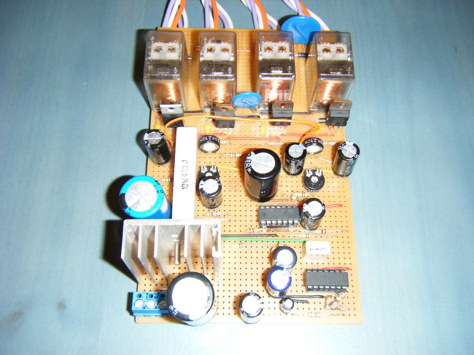
To control when and how much to export to the grid, I needed a way of determining the batteries state of charge. I did this by simply monitoring the battery voltage and switching on the panels when the battery voltage is low while diverting the panels to the grid once the battery voltage reaches a pre-determined high voltage. The circuit below does just that! It monitors the battery voltage in these steps;
- at 27v. Diverts the first 160W to the grid-tie inverter
- at 28v. Diverts the second set of 160W to the grid-tie inverter
- at 29v. Diverts the first 380W to the grid-tie inverter.
- at 30v. Diverts the second 380W to the grid-tie inverter. This actually switches off all charging from the solar panels.
Once the battery voltage goes down again, the circuit will disconnect the panels from the grid inverter and direct the current back to the batteries in reversing order.
As can be easily noted, the export inverter is rated at 500W (Max) while I have double in solar power. Although all panels can be automatically diverted to the inverter, the inverter is only capable of exporting 500W. I know about this limitation and in fact I have left space for a second identical inverter to be installed right below the first.
Being in Winter, I don't have much access energy to export, and in fact the max exported I noticed was 320W and occasionally the first set of IBC panels.
The pictures below is the switching circuit used to control the batteries charging and load diversion. Notice the 4 relays, used to switch the 4 seperate groups of solar panels.