Saturday, May 18, 2013

Greywater System (Update 2)

With reference to my first greywater system which I built a year ago, I can post my review and any changes I made to make the system more efficient.

Well, the first system worked but did not work as well as I hoped for. The problem was mainly the amount of time needed for the system to filter the 100 litre storage tank. Before building the system, I had tested and concluded that a 100 litre would be filtered in a couple of hours. The parallelism of 3 streams which I included should have achieved good results however to my disappointment, it was taking far too long to filter and therefore I was wasting water down the drain.

To speed up the filtration process and not rely solely on gravity I installed a pump. The pump will take water from the buffer tank and pressurise it into the sand filters. At least that was my intention until I installed it and switched it on. After 30 seconds, I identified 5-8 leaks and suddenly one of the sand filters exploded, specifically one of the bottom screwable taps came off together with all the sand! Not much to do. It was obvious that the system coundn't handle any pressure. The drain pipes which I originally used were not the heavy-duty type and I never imagined that a tap would just explode outwards. At this stage I had two options:

1)      Fix the exploded filter (strengthen also the other two) and maybe use PVC glue to fasten the taps once and for all. The problem will be that the sand inside will not be replaceable anymore, something which I didn’t want!

2)      Replace the filters.

I opted for the second option. Although option 1 would have probably worked, I did not want to spend time experimenting with this solution hoping that finally I have no leaks/explosions


 System Overhaul

The changes were mainly at the filtration stage. Both tanks and all plumbing were OK. I scrapped the sand filters and installed four 10 inch standard water filter housing.

The first filter I’ve installed is just after the storage tank, before feeding the pump. It’s a 25 micron wound filter cartridge and its main purpose is to stop particles entering the pump.

The other three filters I’ve installed just after the pump i.e. will be benefitting from the increased pressure. The filters are also the 10 inch cartridges. The filters are;

1)      15 micron active carbon

2)      5 micron

3)     1 micron   

The pump is automatically activated using a float switch installed in the tank and therefore is only active if the tank is full.


Friday, May 10, 2013

Diversion load circuit


Scope

The circuit below has been designed to control the amount of charging applied to my house forklift batteries, while diverting the ‘not used’ power to a small grid-tie inverter. The circuit has been kept simple, minimising cost and making trouble shooting easier in case of problems.

Please refer to the Off-Grid System Update Post for more details.


Circuit Description

The relays contacts have been connected in a way to automatically (while de-energised) route the power to the batteries. Therefore if the batteries are low, no power is wasted to power the circuit/relays! Once the battery voltage starts rising, the circuit will come on, the relays will energise incrementally (depending on the threshold voltages) and power is redirecting from the batteries to the inverter.

Power from the arrays is fed via diodes D10, D11, D12 & D13 to power the circuit itself. The voltage is fed to IC1 - 7812, a linear voltage regulator via dropping resistor R21. The voltage is stepped down to a stable 12v which is used to power the opamps and relays. R21 was needed because the 7812 maximum input voltage is about 35v. This is a bit low considering the voltage coming in from the panels which can reach even 45v (Uoc). Resistor R21 will reduce the input voltage to 20-30v which is within the regulator input operating voltage. Diodes D14 and D15 will increase the regulator voltage by a further 1.4v thus getting around 13v (no load) from the regulator. The circuit voltage is further smoothed and stabilised by capacitor C1, C6 and C7. Varistor RV1 clamps the maximum voltage to 14v.  
The basic principle behind the circuit is simple. Switching is performed by comparing the battery voltage to a fixed reference voltage. Different thresholds have been pre-set thus switching power incrementally at fixed intervals. The four opamps found in the LM324 chip (IC2) have been configured as comparators.

The fixed reference voltage is provided by IC3A. The opamp configuration outputs a very stable 10v through resistor R9. This fixed voltage is applied to the inverting input of IC2 four opamps.
The circuit has got four distinct comparators IC2A, B, C, and D. Since all four are identical, I’ll write only about IC2A. Voltage from the battery is taken via potentiometer POT1 through resistor R20. This voltage is stabilised by resistor R19 and capacitor C11. This will eliminate any sudden voltage fluctuations (which may be caused by sudden huge loads on the batteries or clouds passing over the panels) thus reducing unnecessary switching of the arrays. Further switching stabilisation is also provided at the output of the comparator via resistor R1 and capacitor C2. When the voltage at the non-inverting input (Pin 3 – Connected to the battery sense) is higher that the inverting input (Pin 2 – connected to the reference voltage), the opamp switches on. This will bias the transistor TRN1 which will energise relay RLY1.Once energised; the relay will direct the access power to the grid tie inverter. Diode D1 protects the transistor TRN1 against the relay coil back emf, while LED D5 signals the relay state.

The circuit has been calibrated to divert power at specified battery voltages. These have been set at 27v, 28v, 29, and 30v.


Wednesday, April 3, 2013

Cordless telephone charger (Battery Backup)


Scope

Cordless phones are great! Without going into all their benefits I really like their grid power independence, but there is one problem. Although the cordless phones work on batteries, the base station (and all connecting phones) becomes useless in case of a power failure since the base station needs power to work! To overcome this limitation, I designed and built a simple circuit which powers the base station with the benefit of battery backup.
Although I could have easily tapped a 24v or 12v supply to power the base station from the house batteries, I had a problem with this setup because basically the base station stopped working. In my scenario, I’m also powering the telephone provider modem using my in-house batteries instead of the supplied power adaptor. It seems that the power used for the modem has to be isolated from the power used for the base station. Don’t know why this is but that’s how it has to be!

The requirement was to build a small power supply of 6.5v at a maximum current of 350mA. These are the ratings of the power supply which came with the phone. Here are more details of the phone system and how I'm charging the phones using solar energy.

How it works


AC power is supplied from a 16v ac power adapter, rectified by diodes bridge B1 and smoothed by capacitor C1. LED D8 indicates that the ac power is available. This voltage is then applied to voltage regulator U1, the 1 amp regulator 7812 through diode D1. Diodes D2, D3& D4 will boost U1 output voltage by 0.7v increments and therefore the output from U1 is 13.8v. This is fed to an external battery through fuse F2. The 13.8 volts is enough to keep the battery fully charged or better trickled charged. If this voltage is too high, it can be decreased by removing diodes D2, D3, D4, each diode decreasing the voltage by 0.7 volts.

Diode D5 will direct combined power from the power supply and battery to another voltage regulator U2, the 1 amp regulator 7808.  Diode D5 reduces the voltage and linear regulator U2 will stabilise the voltage to 8v. This is smoothed by capacitor C2 and further reduced by diodes D6 & D7 to 6.8v which is the base station operating voltage. LED D10 indicates that power is being fed to the base station.

Monday, January 21, 2013

Fireplace water heating system (Part 1)

Fireplace water heating system (Part 1)
 
A couple of years ago, we installed a log fireplace at home, a 13KW box from Rotin fires of Zabbar. I'll try to find and post the brand and specification details of the firebox. We light it up only for 3-4 months a year, starting in November/December till March.
These are obviously the worst months for heating water from the sun simply because the days are the shortest and temperatures are the lowest. In fact, during this period we have a deficit of hot water from our water solar heater and we need to boost it up with the electric heating element.
This is why I decided to explore the possibility of heating my solar water tank using escaped heat from the fireplace.
 
The pictures below show what I did to capture heat from the fireplace.
 

The above pictures are a 0.5 metre section of the chimney with a 15 metre half inch copper pipe wound around it. The idea is to capture heat escaping from the chimney pipe and getting it absorbed in the liquid circulating in the copper pipe which will eventually heat up the hot water tank. 


Getting the copper pipe around the chimney pipe proved to be a tough job; in fact I needed help from my two little boys :)

Once the copper pipe was properly wound and secured to the chimney pipe, I used a blanket to insulate the copper pipe from the outside air, thus decreasing heat losses.


The below pictures show the final result. The blanket has been further covered with fibre-glass to further insulate and protect against the elements.

 
I'll be posting another article with all the details of the plumbing and circulating pump once I have everything installed and working.

Monday, January 14, 2013

Off-Grid System (Update)

 
Off-Grid System Upgrade.
 
Thanks to an EU competition, the European Citizens Climate cup , which came to end last May (2012), me and my family placed 2nd with just a 0.5% less reduction in electricity consumption than the winner. I still was awarded €1000 cash to be spent on Renewable Energy stuff. My natural choice was more solar panels :)
I had been planing to upgrade my off-grid system consisting of only 320W of panels for quite some time now and this reward was more than welcome. With the money, I purchased 4 solar panels - IBC Monosol 190MS from Crosscraft. This upgrade of 760W was to increase my off-grid system power production to an STC of 1080W.
The picture below is displaying the mouting of the new panels. These have been mounted horizontally and fitted exactly across the roof. 


Another picture of the new panels as taken from above. The new panels are fixed just in-front of the other grid-tie system panels.


With a new off-grid power generation of 1 KW, I wanted to make sure that no power is wasted once the batteries are full. This can easily happen in Spring and Summer when the days are longer and the load is lower. (Please refer to my separate article titled Off-Grid System for a list of loads being supplied from this setup).
To cater for this access energy, I installed a new 500W grid-tie inverter. This inverter is capable of accepting directly the power from the panels mentioned above and export the power to the grid. In fact the input voltage for this inverter is low (28v - 52v).


My off-grid panels are wired in parallel in 4 groups. The left most DC amp meters records the power coming in from the seperate groups.

 
Group Details:
  • 2 Sharp panels x 80W each = 160W
  • 2 Sharp panels x 80W each = 160W
  • 2 IBC panels x 190W each = 380W
  • 2 IBC panels x 190W each = 380W
To control when and how much to export to the grid, I needed a way of determining the batteries state of charge. I did this by simply monitoring the battery voltage and switching on the panels when the battery voltage is low while diverting the panels to the grid once the battery voltage reaches a pre-determined high voltage. The circuit below does just that! It monitors the battery voltage in these steps;
  • at 27v. Diverts the first 160W to the grid-tie inverter
  • at 28v. Diverts the second set of 160W to the grid-tie inverter
  • at 29v. Diverts the first 380W to the grid-tie inverter.
  • at 30v. Diverts the second 380W to the grid-tie inverter. This actually switches off all charging from the solar panels.
Once the battery voltage goes down again, the circuit will disconnect the panels from the grid inverter and direct the current back to the batteries in reversing order.

As can be easily noted, the export inverter is rated at 500W (Max) while I have double in solar power. Although all panels can be automatically diverted to the inverter, the inverter is only capable of exporting 500W. I know about this limitation and in fact I have left space for a second identical inverter to be installed right below the first.
Being in Winter, I don't have much access energy to export, and in fact the max exported I noticed was 320W and occasionally the first set of IBC panels.

The pictures below is the switching circuit used to control the batteries charging and load diversion. Notice the 4 relays, used to switch the 4 seperate groups of solar panels.


I'll be posting a seperate article to describe how the above circuit works.

Monday, October 1, 2012

Cordless telephone chargers (Solar)

 
Three years ago (Feb 2009) I bought the following Panasonic cordless telephone system from Amazon consisting of 4 cordless telephones; a base unit and another three separate chargers. It works great and can't complain about it.  
Targeting to transform my house into a Zero-energy building, it was time to look at this small energy consumer and upgrade it to charge the telephones (not the base telephone since this needs power 24/7) using small solar panels.
I happened to have previously bought some submersible fountain pond water pumps from eBay for another project. I did use the small pumps but never had found any use for the 7.2v 1.12W panels, well until today! These panels match exactly the chargers for the separate cordless telephones. I plugged in a panel instead of the charger and it has worked OK for the past 45 days, i.e. the small solar panel was enough to keep the telephone batteries fully charged. Obviously, one panel per telephone is needed and the panel placement (in full sunshine) is of great importance to get maximum output from these small panels.

 
Below is a panel, 7.2v 1.12W


I have posted here details for building a simple battery based power supply for the base station.

Thursday, July 12, 2012

Solar Water Heater

Building of a Solar Water Heater.

This article is a description of a closed-loop Solar Water Heater (SWH) I have built and installed at my residence. Although today, the prices of SWHs have gone down in price, (also thanks to the government rebate), I must admit and others who bought a ready-made SWH will agree with me, that the quality of some brands has also gone down! Besides cheap workmanship with some Chinese brand SWHs, one thing I cannot stand is that most of the imported brands can't withstand Malta hot Summer or better have to be manually protected during the Summer months to reduce stress on the system. It's understandable that in Summer (or the warm months), the demand for hot water decreases and therefore only a small percentage of the daily heated water is used, thus hot water accumulating daily in the tank with an increasing temperature. This will pose more stress on the SWH storage tank and other components, resulting in a reduced lifetime! To overcome this problem, most of the installed SWH collector plates are covered in Summer to reduce heat absorption, heating less water and therefore reducing stresses. The SWH described here does not need to be covered, and all components are protected from this problem!

A good reference for starting to learn the basics on SWH can be found on the Home Power magazine web site. Please do visit the site since it will give you a good description of all the components I have used in this system.

System Description:
The system I opted for is a closed-loop, meaning that the sun will heat a liquid which in turn will heat the water though a heat exchanger. Although a closed-loop system is not a requirement for the country I live in since we don't have freezing temperatures and there is no need to empty the system at night, I still opted for this slightly more complicated system for the below reasons;
1) I wanted my home-made solar collecting panels and storage tank to last longer. This can be achieved by NOT passing water through the collector/storage tanks circuit but instead passing glycol. Glycol will not rust and prevents limescale from forming which has the side-effect of decreasing the system efficiency.
2) I did not want my SWH storage tank exposed to the elements, simple because I want it also to last longer. Using a closed-loop system, the storage tank can be easily placed away from the solar collectors
3) Decrease heat lose especially in Winter. In fact I placed the storage tank inside.
4) The SWH I've designed will have two three energy sources;
 - The sun, which will heat up the collector and the storage tank.
 - Log fire. I'll be utilising unused/escaping heat from the fireplace to heat up the SWH storage tank.
 - An electrical element which will be used when the above two sources are not enough

The pictures below detail the construction/function of the SWH.

------------------------------------------------------------------------------------------------------------
The picture below is displaying one of the solar collectors without the tempered glass. The horizontal top (outlet) and bottom (inlet) pipes are 1/2 inch while there are ten 3/8 inch vertical laid copper pipes fixed to a matt black painted galvanised sheet. The total area of each collector is 2 m3.


The image below is showing the two solar collectors mounted facing South with a total collecting area of 4 m3. (The collectors in this picture are not yet connected). The supporting frame used is 3mm
galvanised steel.


The below image is displaying the underneath of the SWH tank. Connections:
1) Two connections inlet/outlet are used for the closed loop solar collector (heat exchanger circuit 1).
2) Two connections inlet/outlet are used for the closed loop fireplace source (heat exchanger circuit 2).
3) The middle large hole will house the electric 2KW element.
4) The other large hole will house the zinc anode.


The image below is showing the interior of the SWH storage tank. Notice the two circuits (left & right interlaced). The vertical copper pipes are about two-thirds the length of the storage tank.


The image below shows my neighbour Mario doing the copper brazing work on the tank circuits. He's a professional machinist by trade and therefore all this was a  piece if cake for him!


Sketch of all the SWH components connected...


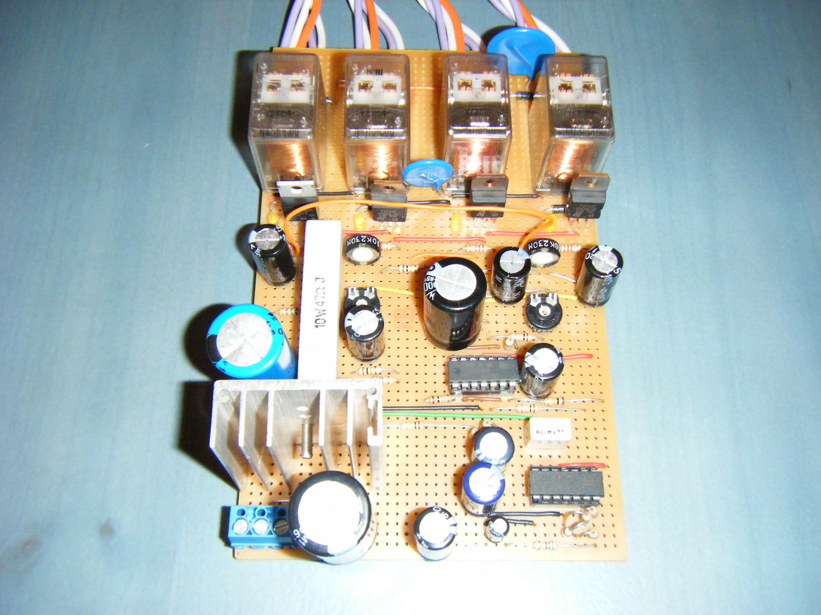
The below image is the 'brain' of the system. Its all controlled by the Steca TR0301 controller. I won't be detailing here all the specifications of this controller however at a glance;
1) Can monitor 3 separate temperatures; Solar collector, SWH tank top and bottom water temperatures.
2) Pre-set with a starting differential temperature of 8°C
3) Cut-off differential temperature of 4°C
4) Cut-off maximum tank temperature of 60°C
5) Holiday function.


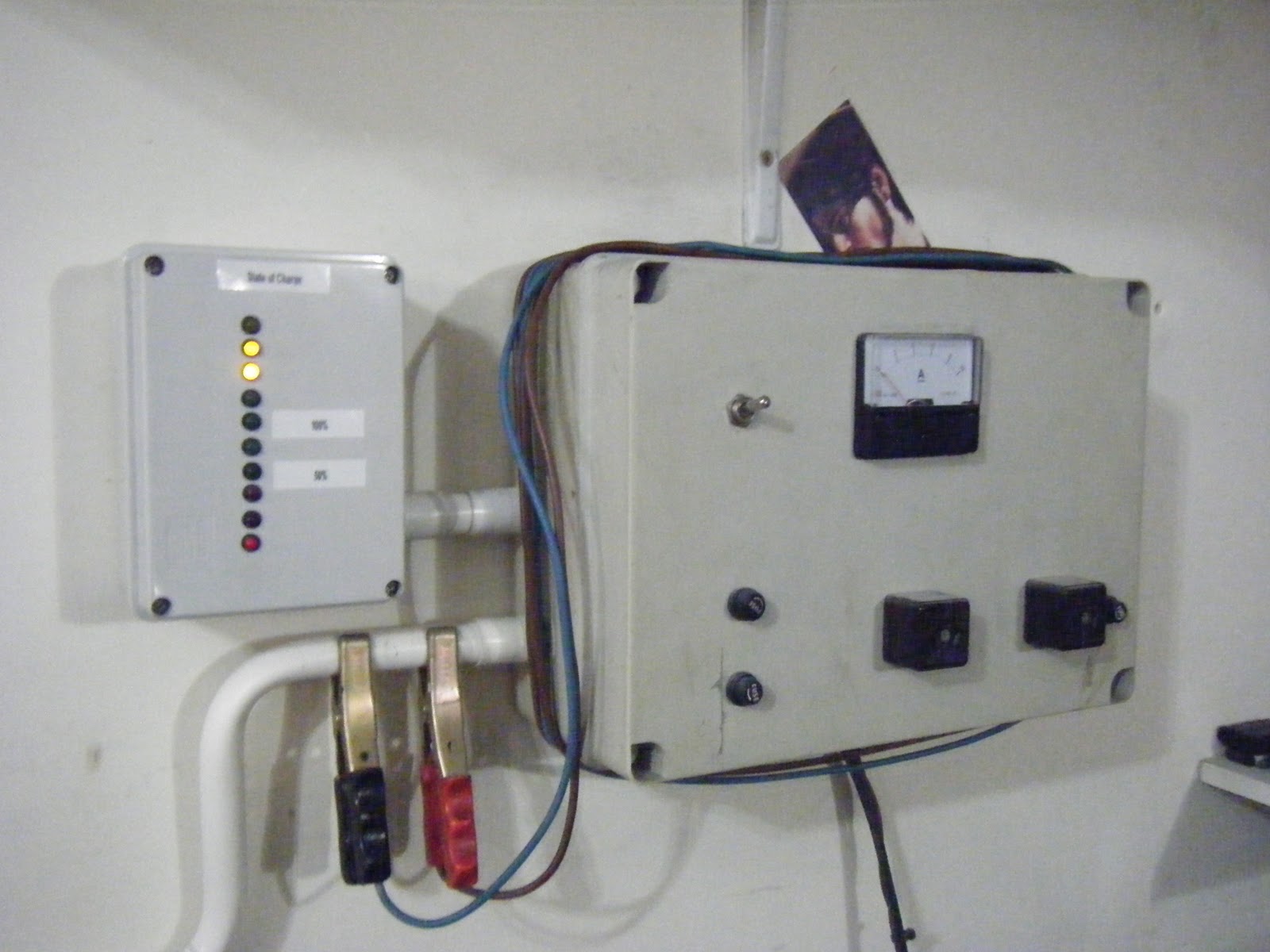
The below image is displaying the SWH components.
 - Top left is the 18 litre expansion tank. When the pressure inside the system increases due to high temperatures, the glycol moves temporarily into this tank to relief the pressure.
 - Below the expansion tank is an MCB box. An MCB is used to manually switch the electric heating element while the second MCB is used to power the differential controller.
 - Next to the MCB box is the Differential Controller.
 - Next to the Differential Controller is the internal circulation pump. This pump is switched on/off automatically by the controller and is used to circulate the glycol around the collector panels and heat exchangers inside the storage tank.
 - On top of the circulation pump is a small pressure gauge, measuring the pressure inside the closed-loop circuit.
- Below the pump are three values used to prime the closed loop circuit.


The below image is displaying the SWH storage tank pipe connections.
- The two top connections are the inlet/outlet to/from the solar collectors closed loop circuit.
- The next two connections are the inlet and outlet for the hot water system.
- The bottom connection is the 'hot' feed to the washing machine.


The below image is displaying the SWH storage tank with all the external components (on the left) and the inlet/outlet piping on the right.

Conclusion.
The system has been in operation since 2008 without any problems. The sun does provide all of my family hot water requirements for a full eight months, while the remaining four winter months are assisted by the electric heating element.
Hopefully I will get all my hot water without using electricity including the winter months, since I'm currently working on the second circuit / heat exchanger to heat also the water using heat from the log fireplace. I'll be posting an article once this is ready and in operation.


Tuesday, May 22, 2012

Product Review - Touch Dimmer Switches

Touch Dimmers Review

This review is for a couple of dimmers I bought directly from TLC.

The Dimmers I'll be referring to are these;
 - 2 Gang 2 Way 400W IQMaster Remote Touch Dimmer Switch (VLIQ1402). Bought two of these.
 - 2 Gang 2 Way Slave Dimmer (VLIQS002). Bought two of these also.


Environment.
Mains System Voltage: 240v
Mains Frequency: 50Hz
Load for the four individual dimmers;
  • 100W (incandescent bulb)
  • 100W (incandescent bulb)
  • 400W (rope light - incandescent bulbs)
  • 100W (5 x MR16 - 20W Halogen)
My intended configuration was to connect the master dimmers and the slave units to enable me to have a 2 way circuits, with the benefit of remote control!

For the benefit of the readers, I have copied below the technical data sheets as listed on the TLC website

iQ - Intelligent Remote/Touch Dimmer Switches
Employ the latest, state of the art, microcontroller based electronic circuitry and use current sensing to compute the load conditions. These products show progressive reaction to overload conditions, depending on the extent of overload as shown in the table below. iQ Intelligent Dimmer Switches are NOT suitable for use with Fluorescent Loads, including Energy Saving Lamps.
iQIntelligent Remote/Touch Dimmer Switches incorporate the following advanced features
Suitable for dimming Low Voltage Halogen lamps via good quality, fully dimmable electronic transformers.


Soft Start, which gradually increases the light output from the load over 1 to 3 seconds after switch on. The Soft
Start feature is also particularly beneficial when used to dim Mains Voltage Tungsten Halogen lamps which have inherent very high inrush current at switch on.

Overload reaction
Case Approximate load Power output to load when dimmer control is on the dimmer as set to maximum a percentage of its maximum rating
1 Up to 125 Load will receive maximum power continuously.
2 >125 to 150 Output to load will be reduced to 50% of the maximum after a delay of approximately 20 seconds after switch on.
3 >150 to 200 Output to load will be reduced to the minimum setting of the dimmer after a delay of approximately 20 seconds after switch on.
4 >200 Output will be disabled (load will be switched off) almost instantaneously after switch on.
iQ Dimmers:
Fused GLS Tungsten Filament lamps to BS161, rated at 230/240V. Dimmable wire wound or electronic Low Voltage Transformers of good quality.
Note: Transformer must be suitable for dimming using phase delay (leading edge) and NOT only phase cut (trailing edge) type of dimmers.
Warning: These dimmer switches are not suitable for use with Fluorescent Lamps or Energy Saving Lamps.

Well, looking at the above specs it's difficult not to be tempted to go for these dimmers! They are practically indestructible thanks to their overload functions, besides their soft start feature which will prolong bulb life.

I did install them however I'm very disappointed and I'm afraid I'll be looking to purchase something else, something better which works well, obviously!

Here is why I'm disappointed:
1) Dimmers get very warm when in use. This may be normal BUT all electronic components will have their working life greatly reduced when working close to their maximum temperature.
2) Dimmers are also warm when not in use. This should not be the case, since the load seems to be fully switched off. This can indicate that either a small amount of power is still being fed to the load or else the dimmer itself is consuming power when not used (the later is normal however it depends how much is the idle power!), both undesirable when my aim is to reduce power consumption.
3) Dimmers are almost all the time reacting to overload when in use. I'm suspecting this, simply because the lamps do not light more then 50%! This should not be the case! There is simply NO overload as can be seen from the loads which I described above which are all within the product specifications. On replacing the dimmer switches with normal switches, the lamps light up without problems. I even tested the circuit with a clamp meter to check for any wiring faults / short circuits and could find none! Once I reset the dimmers, they may work OK for some time and then we're back to an overload situation with just 50% of the available light.
4) Need to switch off the mains supply for the dimmers to reset. Although the specifications read that the switches will reset themselves automatically, they simply DO NOT. I have to turn off the main supply and restore back the power for the reset to work.

Something I did notice last Summer was that when I switched on the AC in the room where I have the dimmers installed, the overload situation disappeared, Yes problem solved! The room temperature was less than 20°C and it seems that this helps the dimmers in keeping them cool and therefore fully functional! To be honest, this is not acceptable because I can't keep the room cool for the dimmers to work!

Hope this review will help others in determining whether this product is a good for them or not!


Friday, January 20, 2012

Greywater System

Greywater System

This article will describe a multi-stage filtration system I built, to collect, clean and re-use water dumped from the washing machine. This water is eventually used as flushing water for a toilet.

The below flowchart lists the main steps I adopted to achieve my goal.


1. The washing machine performs a spin cycle during which water is dumped off.

2. Water from the washing machine is first collected into a buffer tank. The size of the selected tank is 100 litres. This capacity is more than enough to temporarily store a full washing cycle. This tanks serves two purposes;
  • Act as a buffer for the filtration/cleaning system. Since the adopted sand filters take time to filter the water and the machine dumps a large amount of water in a very short time  (during the spin cycle) water needs to be temporarily stored to be slowly processed afterwards.
  • The buffer tank is also trapping 'large' particles and stopping them from moving on to the next stage. This has been achieved by permanently fixing a piece of cloth just on the tank outlet.
3. From the buffer tank, water is passed through sand filters. The sand filters will clean and clear the water. I opted for three parallel filters to speed up the filtration process since the sand filters although doing a great job perform it very slowly!.

4. Water from the sand filters is passed through a 'fine grain' filter during which a small dose of bleach is added.

5. The water is dumped to a 500 litres storage tank. A toilet flushing is connected/fed from this tank.

One key feature of this system is that water flows between stages thanks to gravity! I have arranged the system in such a way as to eliminate the need for pumps which would have added cost to the system besides complexity and electricity consumption.

-------------------------------------------------------------------------------------------------------------------

Since a picture is worth a thousand words, I have taken some pictures of my installation to better illustrate the system.

The below image is a photo of one of the sand filters laid on the floor. It's length is approximately 1 meter and is fully packed by fine grain sand. I've used 110mm drain pipes to construct the body of the filter, blocked at each end by screwable taps.


The photo below is showing an end connector of the sand filter. I drilled the 110 tap and installed a further 15mm adaptor which will be used to connect the filter to the rest of the system.

And this photo is showing the underneath of the TOP tap.

This is the photo of one of the BOTTOM taps. I have covered the outlet with a thick cloth (similar to what I did inside the buffer tank) to restrict sand getting out from the bottom of the filter. It turned yellow because of the glue which I used when it settled.

The 100 litre buffer tank, mounted on steel brakets using nine 8mm stainless raw bolts.

The buffer tank feeding the three parallel sand filters.

Displaying the three sand filters paralleled fed from the buffer tank and in turn feeding the 'fine' filter.


This below photo is the 'fine' filter which further cleans the water. I have placed bleach tablets inside this filter before feding the 500 litres storage tank.


The 500 litres storage tank.


The toilet flushing modification. Switching between greywater and the normal main water is just a matter of closing an angle valve and opening another, as shown below.

 
Note. Some parts of this system have been replaced as detailed here.

Wednesday, November 9, 2011

Off-Grid System Setup

Off-Grid System
My off-grid systems have been online for the last 5 years, installed in 2006 and basically consists of a primary 24v setup and a secondary 12v setup. My scope for this setup is twofold,
  1. Have a backup system in case of a system outage. Although it will not power and provide all my electricity needs, at least it will handle the basic. 
  2. Reduce my electricity consumption.
Specifications - Primary System (24v):
System DC voltage: 24v
Solar Panels: 4 x 80W Sharp panels, totalling 320W.
Wind turbine: Modified 400W Air-X Marine wind turbine. Details of the modifications can be found in this post.
Batteries: 2 set of 24v fork-lift batteries. Total of 12 batteries per set @ 2v per cell. (about 8 years old when I took them and unfortunately had been heavily abused - sat discharged and lacking electrolyte for a long time and therefore the plates have been exposed to the air and most probably are heavily sulphated). No idea about their current capacity; although I'll measure it and post my findings in a separate post, however they are very, very heavy and each cell physical size is:
  Set 1: 20cm width x 15.5cm depth x 40cm tall
  Set 2: 20cm width x 12cm depth x 46cm tall

Note: These batteries have been changed to a new set. Details can be found here.

Inverter: Modified BEST FORTRESS UPS 600VA. This is basically a computer UPS, with these modifications;
  1. Removed the two internal 7AHr batteries and instead redirected the UPS to get it's power from an external source, i.e. the fork-lift batteries.
  2. Removed the internal beeper which acted as an alarm when the UPS was operating on batteries. Obviously in this case I didn't want the beeper to sound for 24 Hrs a day!
  3. Installed two CPU fans to help in cooling. This UPS relied exclusively on convection for cooling. Since this UPS was going to be used 24Hrs a day and in inverter-mode, it was getting quite warm especially in Summer due to the higher ambient temperatures. I therefore built a circuit to automatically switch on the fans when the UPS internal temperature reached a certain threshold, set to approximately 40°C. The circuit can be found here.
Desulfator: Infinitum 24v battery life optimizer.

Specifications - Secondary System (12v):
System DC voltage: 12v
Solar Panels: Two small panels totalling about 40W
Batteries: 1 set of 200 amp hr ex telecoms batteries.

--> Update! Batteries & Panels have been upgraded/replaced!


Usage:
My house loads are the majority 240v 50Hz AC, however I do have some loads which work directly from the DC batteries.

I've listed below the pros and cons of a DC system versus an AC system.
Advantages:
  1. Running DC loads will eliminate the inverter inefficiencies.
  2. Transformers and/or chargers inefficiencies are also eliminated (or reduced).
  3. The inverter can be lower rated since it won't need to handle all the house power.
Disadvantages:
  1. DC appliances may be more expensive to purchase.
  2. DC appliance may be more difficult to source especially from local suppliers.
  3. A separate DC wiring infrastructure is needed.
  4. Since DC wiring is low voltage, compensation for voltage looses will have to be made up using extra thick wiring.
DC loads
Having said all this I still opt for DC loads when possible. Although my DC load is limited, it currently consists of;
  1. Several 12v DC LED lamps (installed in the kitchen).
  2. Several 12v DC halogen lamps (installed in the kitchen cupboard).
  3. 15'' Digital picture frame.
  4. Cable modem (TV, Telephone and Internet).
  5. WIFI router 
  6. Reverse Osmosis pump
  7. Well-pump automatic relay circuit.
  8. House alarm DC supply.
  9. Weather station - step-down to 6v.
  10. Walk-in wardrobe lighting.
  11. Chimney space heating.
  12. Electric Shoe Dryer.
  13. Wardrobes Internal LED lighting. These are enabled automatically on opening the wardrobe doors.
  14. Panasonic Cordless Base Station
 AC Loads
Currently the inverter powers;
  1. All the house lighting.
  2. TV, DVD, decoder, Hi-Fi.
  3. Solar water heater circulating pump.
  4. Multiple 13amp socket outlets distributed across the house.
 -----------------------------------------------------------------------------------------------------------------------

Below I have attached  pictures of my system.

24v battery sets. Both sets are enclosed in wooden boxes to disable access to my two small children to the battery terminals! Batteries are located in the garage so no problems with regards to heavy gassing.


The 4 Sharp solar panels configured in series/parallel. Each set is installed on it's own pole and feeds its own on/off switch,fuse & amp meter (as shown further down on the DC monitor box). I'm running a common negative 20mm wire for the panels while using a 4mm wire for each set of panels.


General view of my garage wall. Several components are being displayed, listed below;


1) The yellow box is the SMA grid-tie inverter.

2) Below the SMA inverter is the main change-over switch which is used to switch over the house lighting circuit from either the inverter or the local utility provider. The three meters on the same box are a frequency meter, an AC voltmeter and an AC amp meter.


3) The box left of the SMA inverter is a DC junction box with 300 amp switches. 1 red switch is used for the inverter, while the other red switch is a two position switch connected to both 24v battery sets.


4) The 600VA inverter is located on a small shelf (top right hand corner)

    5) Below the 600VA inverter are the wind turbine electronics.

      6) Next to the wind turbine electronics box is located a 24v DC meter box (details just below).
      7) The small box located at the very bottom is the 12v DC meter box (details further down below).

      Below is photo of the several DC meters which I use to monitor the system.

      1. On the left are four DC amp meters, feed from the solar panels.
      2. The right-most meter is an amp meter fsd 10amps used to monitor charging from the wind turbine.
      3. The middle top meter is a 30v fsd meter
      4. The middle centre meter is a 30 amp meter. It measures the total charging current (Solar + Wind + Charger)
      5. The middle bottom meter is another 30 amp meter measuring current consumed (Inverter + 12v Chargers + DC appliances)
      The picture below is displaying the 12v DC meters.


      The box above serves three purposes.
      1. Monitor 12v system. The left meter is a 5 amp meter measuring the 12v DC load. The right meter is another 5 amp meter measuring the 12v DC charging current. (Solar Panels + Wind Turbine + automatic charger)
      2. Controls the 12v system.The bottom left switch and fuse control the Power out. The bottom right switch and fuse control the Power in.
      3. 12v automatic charger. The internal charger monitors the 12v batteries and if the voltage falls below a certain threshold (currently set to 12.4v), the charger automatically kicks in down-converting power from the 24v system. The charger remain on for 5 mins (irrespective if the voltage went up), after which it switches off. If the battery voltage is still low, the charger will switch on again, repeating until the battery voltage is above the threshold. The centre LED indicates when the charger is ON. The charger is based on the popular 7812 (1 amp) fixed voltage regulator, having it's current output increased to 8A thanks to two 2N3055 transistors, mounted on top to help dissipate heat. The heat sinks are clearly visible...


      The below two boxes are;

      The left box is an LED voltmeter for the 24v system used to indicate the State of charge (SOC).


      The right box is a 12v battery charger, taking it's power from the 24v system. The charger is based on the popular 7812 (1 amp) fixed voltage regulator, having it's current output increased to 8A thanks to two 2N3055 transistors mounted inside the box. This charger is mainly used to charge any 12v batteries such as our cars starting batteries.

      The below photo is showing a 24v charger. Nothing fancy about it. Just a transformer, two 35amp bridge rectifiers in parallel mounted on a heat sink and a large electrolytic capacitor to smooth out the output. This charger is only used in emergencies, i.e. when the batteries SOC goes down below 50% and no charge from the solar panels is available.