Monday, August 14, 2017

Panasonic Base Power Supply

I have setup a Panasonic KX-TG8424EB 4 set cordless telephone system at home. All telephone Bases use a 6v power supply. 
I have managed not to use the chargers on the phones and instead installed 7v solar panels, which is enough to charge the individual phones during the day. Details can be found here.
However, the Base charger needs to be always on since it needs to receive and transmit the telephone conversation. 
I discovered that the Base station cannot use the same 12v supply rail as the router (through which the telephone system is being received). I therefore needed an isolated power supply for the base station.
I found the below DC Converter isolator online. It receives a maximum of 12.6v and outputs (totally isolated) 12v. This device can handle 250mA working at an efficiency of 75%. I opted to parallel two isolators instead of one to get more current output. 


The below circuit basically needs a 12v-24v input from the house batteries and outputs an isolated 7v supply for the base unit. 


Circuit Description:
The circuit is pretty easy and straightforward. The input is limited to 12v using the U1 7812 voltage regulator. During the day when the 12v batteries are charging, the voltage may even go up to 14v enough to burn the isolators so better safe then sorry! The 7812 voltage regulator will always maintain the input voltage to the isolators at 12v.
Output from the isolators is fed to a 7808 voltage regulator where it is further smoothed and fed to the base unit.

Parts List:
D1, D2 - 1N4001
D3 - Green 3mm LED
D4 - Red 3mm LED
U1 - 7812
U2 - 7805
U3, U4 - HDN3-12S12A1. Isolated Power Supply Module 12.6v In / 12v Out, 250mA.
R1 - 1K
R2 - 1.5K
C1 - 4700uF 25V
C2, C3 - 2200uF 16v
C4, C5 - 0.1uF

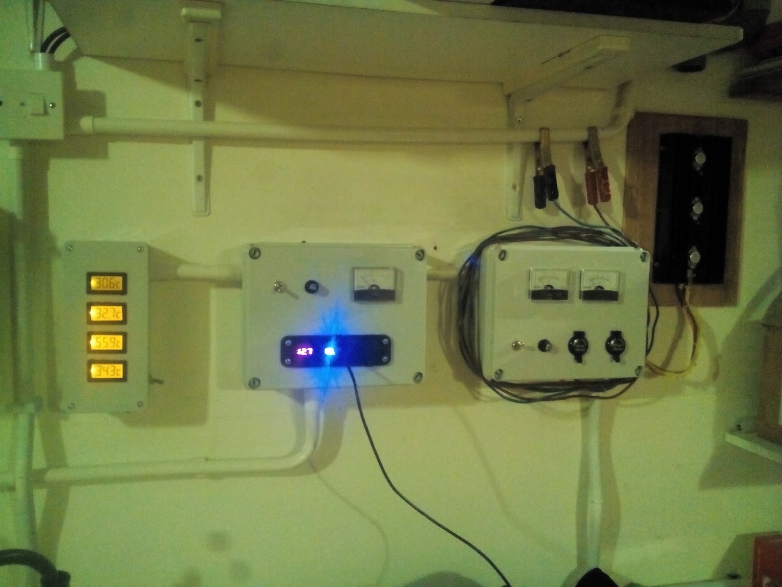
The pictures below are showing the finished circuit. Notice that both voltage regulators are fitted to a heatsink.


Saturday, August 12, 2017

12v Supply Station


As part of my house electrical installation, I have installed a 12v DC station. Supply is taken from the 12v DC batteries and delivered through a cigarette lighter adapter and 2 x USB Chargers.

I installed the below adapter which contains;
  • A Cigarette lighter
  • 2 x USB outputs
  • Digital voltmeter.

The unit is fused and a 5 amp analogue meter displays has been installed to measure the current consumption.


There isn't much inside the box, just the 3 large smoothing capacitors and all the necessary connections.


The image below is displaying the 12v Supply station installed between the Temperature Monitor (Left) and the Battery Charger (Right).


Temperature Monitoring

Temperature monitoring is critical for the correct function of any electronic system. Once an electronic component heats up, it can either shut down or else short circuit. The latter can result in over current and eventually fire (if no suitable protection has been installed).

I bought the below temperature meters from eBay. They seem to be designed to be installed in computer cases to measure CPU temperature. They come with a couple of meters wire probe length, however this can be very easily extended.


The meters are powered from the 12v battery system, using a 7805 voltage regulator to supply them with a 5v DC supply.


The image below is displaying 4 different temperatures as measured on a August afternoon at about 14:00.


  • The Top display is the room temperature, i.e. in my case, the garage were I have all electronics & batteries installed.
  • The 2nd display is monitoring the temperature inside the shunt box detailed below. Installed are 5 x 50 amp + 2 x 100 amp shunts, together with fuse holders.
  • The 3rd display is monitoring the temperature of the off-grid inverter. Note that the temperature sensor is install on the outside of the inverter. Eventually I'll place it inside and will therefore read a higher temperature.
  • The 4th display is showing the SMA 2KW grid-tie external heatsink temperature.

The image below is displaying the temperature meters as installed together with the other components in the garage.


Capacitor Bank

Since I have a number of DC appliances which are using directly both the 12v & 24v supply rails, it was imperative that I make sure that my DC supplies are as smooth as possible, without any spikes and with the least amount of voltage fluctuations.

A list of appliances which are utilizing directly the DC supply rails can be found here. Loads with motors will generate spikes and back-emf. In my case there is the Reverse Osmosis pump and also In Summer I utilize multiple low voltage pumps to circulate water for the pool.

The below image is displaying the capacitor bank / protection devices installed. 


Actually there are 2 separate circuits, a 12v (top board) and a 24v (bottom board). Both circuits are almost identical except for the components working voltages.
The circuits consist mainly of the following components;
  • Large electrolytic smoothing capacitors. When a huge DC load is switched on, this will starve temporarily the DC lines, i.e. due to a higher current demand, the voltage will go down. These large capacitors will smooth this effect.
  • Smaller electrolytic smoothing capacitors with a low ESR (Equivalent Series Resistance). These capacitor also offer a smooth DC voltage when a huge DC load is switched on. The added benefit of a low ESR is better ripple suspension.
  • Non electrolytic  capacitors. These capacitors offer high frequency suspension on the DC lines. (I have installed 4 Battery Desulphators, 2 per battery bank, and since these work by generating high frequency pulses, I though to be safer if I also compensated for these pulses not to reach my appliances).
  • Multiple voltage varistors. Varistors, also known as voltage dependent resistors work by varying their resistance varies with the voltage. In this case, if the DC voltage for the 12v supply reaches 14v+, the varistor will shunt the supply rail thus preventing the supply rail from reaching excessive voltages. Same for the 24v supply, If the voltage tries to exceed 32v+, the respective varistors will shunt the supply rails.
  • Blocking diodes. These diodes are fitted in reverse order thus they will only conduct and will suppress any back-emfs

Parts List:
  1. C1-C3 --> 100,000uF 63v
  2. C4-C8 --> 470uF 50v Low ESR
  3. C9 - 470nF
  4. C10 - 0.1uF
  5. C11 - C13 --> 100,000uF 25v
  6. C14-C18 --> 470uF 50v Low ESR
  7. C19 - 470nF
  8. C20 - 0.1uF
  9. D1 - Orange LED (24v)
  10. D2 - Yellow LED (12v)
  11. D3, D4 - 7amp Diode
  12. R1 - 1.2K
  13. R2 - 2.2K
  14. VAR1 - VAR5 - 32v Working Voltage Varistors
  15. VAR6 - VAR10 - 14v Working Voltage Varistors


Monday, July 24, 2017

Product Review - Schneider Xantrex C35 Charge Controller

To protect my 2 x 6v Trojan Batteries, I bought and installed a Schneider Xantrex C35 Charge Controller.

The Controller is fairly easy to setup and it comes with a comprehensive manual. It's very difficult to get stuck with the installation or wrongly configure the controller.

I installed a dump load to divert excessive power. I still have to find or build an aluminium box for the diversion load heater, in fact right now it's just hanging underneath the controller.  The dump load can easily handle 12 amp at 12v.


I have installed the controller a month ago and I can confirm that the batteries have never been overcharged. In this small installation I do have more power then needed and therefore without the controller I'll be boiling the batteries on a daily basis.

The photo below is displaying the 12v Control box and next to it the charge controller.


The dump load has been enclosed in a box...


iMiev AC/Heater consumption

The iMiev is designed to deliver 160KM on a single charge. According to the official iMiev specifications this range can greatly vary depending on a number of factors. 
As detailed below (taken from the iMiev specification small print) , the electric range can and will vary depending on the driving style, traffic conditions. ambient temperature and use of AC.

*2: NEDC stands for New European Driving Cycle. The values of electric energy consumption and electric range are based on UN R101. These values vary depending on driving style, road and traffic conditions, ambient temperature, use of air conditioners and so forth.


I'm gathering statistics on my iMiev on a monthly basis and can confirm that yes, using the A/C or Heater will greatly effect the electric range. 


The photo above was taken on starting the car and with the A/C on. The car was standstill. As can be clearly seen, the Power meter was not on Zero but the needle moved to 'Eco' which means that power was being taken from the traction battery. The consumption is not that high but normally without any A/C switched on, and the needle in that position, I'll be driving the car at 40KM/Hr on a flat surface!
Therefore it is clearly obvious that cooling/heating does consume power from the battery, thus reducing the electric range.
I'm not fanatic about the range I manage to achieve, I'm more interested in driving in comfort.

Wednesday, July 19, 2017

Fire Prevention

If you go through my blog, you'll find out that I have all the house batteries and almost all power electronics installed in my garage (which is physically linked to my house).


The photo above is showing part of my setup. 
  • Burglar Alarm (12v sealed battery inside)
  • 4 x 12 MCB boxes. 240v AC House circuits.
  • 2KW SMA Inverter (Yellow Box)
  • House Power selector switch and meters with surge protectors inside
  • 12v Control Box with a xantrex charge controller c35. All Fused
  • 24v Control Box. All Fused
  • Battery and Inverter Switches
  • Off-Grid Inverter
  • 2 x 500W Grid-tie Inverters
  • 12v Car Battery Charger
  • Battery Box (12 x 2v Forklift Batteries + 2 x 6v Trojan Batteries)
All of the above can catch fire!
Everything is fully fused as it should be and all wires are properly sized to carry the estimated current, however this does not mean that accidents cannot occur... an electronic component malfunctions and the fuse does not blow or blows late after a copper wire catches fire.

To put my mind at rest I installed two fire extinguishers in the garage.
  1. 6kg Dry Powder extinguisher
  2. 5kg CO2 extinguisher
Both can be safely be used on electricity although I'll prefer the CO2. Having said that in large open spaces, the CO2 may not be enough to extinguish the fire and that's why complimenting with a dry powder extinguisher is a good idea.   


Above - 6kg Dry powder


Above - 5Kg CO2


Tuesday, July 18, 2017

Battery Desulfators

Basic technical information.
Basically, lead acid batteries are made up of lead and lead dioxide plates immersed in an electrolyte or sulfuric acid.
During normal use the sulfuric acid reacts with the lead dioxides plates to generate electricity (i.e. power) and in the process a thin layer of solid lead sulfate crystals are deposited on the plates. If inspected, these crystals will cover the battery plates and looks white as shown below.


This hardened lead sulfate is an unwanted product of this chemical reaction and is called sulfation, one of the main reasons why lead acid batteries start loosing capacity and eventually become unable to hold any charge and need to be thrown away. This happens because these large crystals clog the pores of the lead dioxide active material and therefore charging becomes impossible.
During charging, the reverse process occurs and the lead sulfate is converted back to lead dioxide and sulfuric acid, restoring the battery to it's pre-discharge state. Unfortunately, this charging process is not perfect and in fact with every charging/discharging cycle, more sulfate is deposited on the plates and never removed, thus the battery loosing slowly it's original capacity. That's why a battery is also rated on the number of cycles it can sustain. A cycle is considered to be a battery from a charged state, discharged and charged again. Expensive fork lift batteries are rated to sustain > 3000 cycles i.e. if the battery is charged/discharged daily, the battery can survive 8+ years with very little loss of capacity!
A battery desulfator is a device which will clean the batteries internal plates, i.e. it's able to remove the hardened crystals (which were not previously removed by the normal charging process) and restore the battery to a better state, holding more charge and capacity. A good desulfator uses pulse frequency to dissolve these crystals.

There is a lot of literature and videos on the internet about Battery Desulfators however all seem to lack to draw a definite conclusion, do Battery Desulfators really work?

Deep Cycle Batteries are expensive! In fact I preferred to spend extra Euros on the Desulfators in the hope that they will maintain my batteries in better shape and prolong their useful life.

Installation
I opted for these Battery Desulfators from infinitumstore. I like their design, fully enclosed/sealed making them ideal to sit next to batteries. Also these devices use Amplitude Modulated Pulses at the resonance frequency of the crystals to shatter the covalent bonds that hold it together.

I installed 4 desulfators in total, 2 in parallel for the 24v forklift batteries while another 2 desulfators in parallel for the Trojan 12v system.

The image below is showing the installation details.

  • The top 2 desulfators are 12v
  • They are installed just after the 12v battery main switch. I used an old (but unused) 240v AC 45 amp fuse box, containing a 30 and 15 amp fuse inside. I used the 30 amp as the 12v battery main fuse, while the 15 amp fuse holder for the 12v desulfators. I did replace the desulfators 15 amp fuse wire with a 5 amp fuse wire.
  • The bottom 2 desulfators are 24v
  • They are also installed just after the 24v battery main switch. I used an old (but unused) 240v AC 60 amp fuse box, containing two 30 and one 15 amp fuse inside. I paralleled the 30 amp fuses as the 24v battery main fuse, while the 15 amp fuse holder for the 24v desulfators. I also did replace the desulfators 15 amp fuse wire with a 5 amp fuse wire.
  • All components have been fitted to a piece of wood which in turn was fitted against the battery box.


The desulfators have been installed just against the outside of the battery box.


Monday, July 10, 2017

Heatsink Water cooled


Introduction
On upgrading my off-grid 24v system, I added more Photo-Voltaic Panels - 900W in total (150w x 6). I decided to sell this all this power instead of storing it into the batteries. I purchased two small grid-tie inverters - 500W peak  each and connected them to the solar panels and grid. They worked well however I noticed that the inverters were getting pretty warm! The inverters are installed in the garage which is South facing. Therefore the garage is exposed to long periods of direct sunlight, raising the room temperature significantly. I measured the temperature in the afternoon and the mercury hit 35 °C. This was forcing the inverters fan to run continuously besides that the inverters were still getting pretty warm.
I needed to find a way to keep the inverters cooler. One way to do this was to water cool them!
This required a lot of preparation because I needed to have a cold water supply next to the inverters, something which was not readily available.  The water cooling supply has been taken from the roof tank (2 stores higher) and thanks to gravity, I did not need a circulation pump to get the water circulating the inverters. The water after passing through the inverter heat-sinks is then dumped back in the well, thus there is no water wastage. The house water well pump would then switch on occasionally automatically (depending on the roof tank water level) and new cold water is pumped from the well to the tank.
I have this system running for the past month now and must say that I'm really satisfied with it's performance. The main objective has been reached in that the inverters are now running much cooler. A cooler inverter (electronics) will translate to a longer working life. The water is being circulated against the heatsink for most of the day but that's OK as long as the inverters are kept cool.

Built Details
The Inverters have been mounted on a 4mm aluminium sheet. A large heatsink has also been fitted to the back of the aluminium sheet to add in thermal mass. Thermal paste has been used to facilitate heat transfer between the two metals.
Two CPU water cooling blocks (as shown below) have been fitted to the 4mm aluminium sheet to allow cold water to circulate and cool the heatsink/inverters.

One Thermal switch has been fitted to the heat-sink. I have chosen a switch which will operate at 35 °C and reset at 20 °C. Therefore once the heatsink temperature reaches 35 °C , the thermal switch will turn on... switching on the water circulation solenoid.


The picture below is showing the underneath of the inverters heatsink. In the middle, I have attached the heatsink, on the left top corner, I have attached the thermal switch while CPU cooling blocks are the blue blocks attached to either side of the heatsink.


Water flow is controller using a 24v AC solenoid valve. A small transformer has been fitted to power the solenoid since it runs on AC! 
An AC solenoid runs cooler than a DC solenoid and that's why it has been chosen.


The picture below is showing the front of the aluminium sheet with the grid-tie power inverters installed.


The picture below is showing the inverters installed to the wall. On the left there is a consumer box with 2 separate double pole MCBs and a KW power meter to measure the amount of power generated by these inverters.
On the left of the inverters, there are the water connections, water feed and return showing also the solenoid box at the extreme right.


The solenoid box installed. A relay has been used to power the transformer which in turn will power the solenoid valve.


Therefore in summary;
The heatsink will warm up. On reaching 35 °C, the thermal switch will close and this will activate the 12v relay coil. The relay contacts will close and this will activate the 24v AC solenoid valve, opening the water flow.


Trojan 6v T-105 Deep-Cycle Flooded

The 12v system batteries have been replaced with 2 x 6v Trojan Batteries rated 225 Amp-Hours at the 20-HR Rate. Details about these batteries can be found on the Trojan website or here 

The batteries have been installed in the battery box to 
1) Eliminate any accidental contact with the terminals. A short circuit on the terminals can easily promote a fire. If a metal object drops on the terminals, a huge current will pass through it. In a matter of seconds the metal object will get so hot that it would be impossible to remove, it may even weld itself to the terminal blocks. This huge current will cause a huge sudden discharge during which the batteries will get hot and may explode.
2) Deep cycle batteries tend to gas heavily during charging. This gas is highly explosive and a spark can easily ignite the gas causing the batteries to explode. The battery box which I have installed is well vented so this possibility is further reduced.


These batteries will be charged using 2 panels.
thus a maximum of 17 amps charging can be reached during the day. A Schneider Xantrex C35 Charge Controller has been installed in 'Diversion Mode' to protect the batteries from overcharging.

Friday, December 11, 2015

Paris has become Greener.

Last week I was in Paris for a short holiday and on arriving at the airport, the first taxi which I took was a hybrid. At first I thought that it was a coincidence, but then I started noticing that a good percentage of the Paris taxi fleet were actually hybrids ranging from PeugeotRenault, Citroën to Toyota.

I also noticed that a number of EV charging points have been installed across Paris since my last visit there 2 years ago, with EVs parked and charging. I found out that Paris has introduced an electric car sharing program and through my experience and judging by the EVs which I saw in the streets, I can say that it's being used quite a lot.

In the past 2 years a lot has changed in Paris and now it has become more Green!


Since I happened to be in Paris in December 2015, when the 2015 United Nations Climate Change Conference talks were being held, I was lucky enough to see a large display of Photo-voltaic panels installed in Champs Elysees serving as a demo to the public on the use of the sun to generate electricity.


I also saw a number of new Hyundai ix35 Hydrogen fueled cars (to be used as Taxis) just in front of the Eiffel Tower. Some more details on this initiative can be found here.


Friday, August 28, 2015

13 Amp 2 Gang Double Switched Socket c/w USB

Product Review - 13 Amp 2 Gang Double Switched Socket c/w USB


I bought a couple of these 13 Amp 2 Gang Double Switched Socket c/w USB from TLC Direct some time ago.


I have tried charging mobiles, wireless headphones, tablets and mp3 players with success! These devices do work well. Since the output is limited to 2.1amps, it means that only 1 amp is available per USB port. That's fine for mobiles, headphones and mp3 players however the tablets will take longer to charge due to the smaller charging current.

These Sockets are really cool. You won't be wasting a 13amp outlet for a charger anymore!

Monday, August 3, 2015

The Electric vehicle arrived!

Finally the much awaited Electric vehicle (EV) Arrived. I Obviously went for the Mitsubishi iMiev which I bought from Mitsubishi Motors.
Having thoroughly tested the car for 8 weeks last year as part of  an EU Demo program, funded by the EU, (Demonstration of the Feasibility of Electric Vehicles towards Climate Change Mitigation) Project no. LIFE10/ENV/MT/088), it was the natural electric car for me to buy.

I had blogged about my 8 week experience here.

I have also linked to the Mitsubishi Motors website for a list of the car's features and characteristics.

The EV has been in service for almost a month now and I have started gathering some real-life data here.