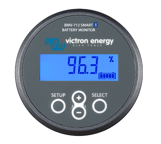
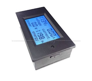
One of the first tasks I assigned myself on purchasing the yacht was to install a battery monitoring system. After some research I opted for the Victron BMV-712 Smart monitor. This model has Bluetooth built in which is a huge benefit considering that you can access the monitored data from the comfort of the mobile.
Brian Ellul
Thursday, April 20, 2023
Battery Monitoring System
Inverter Installation
The Inverter circuit breaker has been fitted under the main saloon seat just next to the inverter.
- 900W Toaster
- 1200W Electric Kettle
- 240v AC points
- Small (10litre) air compressor
- 240v Water pump (used to flush the black water tanks & Deck wash)
Water Expansion Tanks
Why install an expansion tank?
Well the answer depends if it's installed on either the cold or water circuit.
- Cold circuit.
On the cold circuit, an expansion tank is not really indispensable however I installed it because it will reduce the number of times the water pressure pump switches on. The pump will not switch on every time the water tap is opened. Once it's on, it will fill up the expansion tank (depending on the size of the installed expansion tank) and any subsequent water usage is supplied from the tank until the pressure falls enough that the pump will need to switch on.
The installation of this expansion tank is a huge benefit especially at night because the pump will not switch on as soon as the water tap is opened. The pump although enclosed is not very silent and at night it just wakes everyone up when it switches on!
- Hot circuit
In this case, personally I think that an expansion tank is indispensable. The expansion tank is designed to handle the thermal expansion of water as it heats up in the water heater, preventing excessive water pressure. If water pressure gets to high it can damage valves in plumbing fixtures, joints in supply pipes and the water heater itself.
Fridge Extra Cooling
Thursday, February 13, 2020
Grant on renewable batteries
This will eventually get even worse for more people who have installed solar panels simply because the initial contracts for selling RE units to Enemalta are expiring. During the contract, the selling rate was €0.21 or €0.25 for Gozo (energy generated from the solar panels and sold to Enemalta), the intention being to make it higher than it's bought from Enemalta making it more attractive for people to invest in solar power generation due to the higher selling rate per KW and thus a better return on investment.
However the intention of all this is now clear! Enemalta will encourage clients to install panels and make some money for the first years (actually the first years are used to pay back the initial investment), THEN, it will pay you back a miserable rate, enough so the company can make money. Here we're talking of a minimum of €0.05 per KW profit.
Wednesday, February 12, 2020
EV Licence
I have to mention this since instead of progression we're experiencing regression at Transport Malta!
The government 2-3 years ago waived the €10 licence fee for electric cars and in fact it's now free which is a good thing.
However I would have preferred to still be paying the €10 licence fee simply because now the licence can't be settled online.
It seems that instead of putting more services online, Transport Malta have opted for us, electric car owners to pay them a yearly visit at their office just to settle the license fee.
Why can't it be done online anymore? Why do I have to go personally to their office? Is it worth to save €10, you need to go personally to their office? Is this the way forward?
Thursday, July 18, 2019
Solar Inverter Diversion
Lately I have upgraded by 12v battery system by adding an extra 150W solar panel to the existing setup, totaling my 12v system to 320W (STC). I just have a small limited number of circuits/load on this system and was wasting a lot of power through the Xantrex charge controller configured as a diversion load. On a sunny day, the charge controller was diverting power to a power resistor before noon, wasting power as heat for the whole afternoon.
To make better use of this power, I installed a 12v 1000W grid-tie inverter. The idea is to divert the excess power to this inverter once the batteries are full and use only the charge controller as a fail backup if there is no grid power.
Circuit Diagram
The circuit is fairly simple and I tried to keep it that way! I always follow the KISS principle (Keep it Simple Stupid).
The circuit below is used to switch on/connect the inverter to the panels/batteries once a threshold voltage is reached and then disconnect the inverter after a pre-determined amount of time. I did NOT use a low voltage disconnect and opted for a timely disconnect simply because this will cause the inverter to connect/disconnect too frequently.
Supply for the circuit is taken from a 24v supply rail (another set of batteries & panels in my case) and this is stepped down to 15v using the 7815 linear voltage regulator. This 15v will power the whole circuit. Capacitor C2 is used as a charge reservoir to maintain a steady 24v supply to the 7815 voltage regulator. Diode D7 (Green) signals that there is a supply voltage on the circuit board.
I have used another voltage regulator 7810 to get a 10v supply. This voltage is divided by resistors R1 & R4 which will give me a 5v signal voltage. This voltage is made steady thanks to another reservoir capacitor C3. Capacitor C6 is used as a charge reservoir to maintain a steady 24v supply to the 7810 voltage regulator
The 12 volt detection is carried through Diode D4, split by potentiometer R2 and smoothed by capacitor C4. Any quick variations in the 12v system are simply filtered out through R2 and C4, thus providing a pretty steady signal to the opamp. This will eliminate any 'quick' variations to the supply rail such as switching on heavy loads or panels cloud effect or even the switching on itself of the grid- tie inverter.
The opamp is an LM324, and I'm using just one opamp out of the four available. The opamp is configured as a differential comparator.
The opamp feeds the base of a bipolar transistor Q1 - TIP122 which in turns powers the relay. Diode D2 protects the transistor from any back emf generated by the relay coil.
Diodes D3 and D8 safeguard the circuit from accidental reverse polarity.
The non-inverting input of the opamp is held at about 5v thanks to the R1/R4 voltage divider. The inverting input is connected to the 12v signal detection. As the battery voltage rises, it slowly starts charging capacitor C4, a 10000uF capacitor. Once the inverting input exceeds the non-inverting input, the opamp output switches on. Orange LED D6 is on. Capacitor C5 starts charging through diode D5 and this will provide a base current to transistor Q1, switching on the relay and connecting the grid-inverter to the grid.
Once the inverter is on, the batteries will start draining heavily and thus the signal voltage will lower down, The non-inverting input will become more then the inverting input and therefore the opamp output switches to low. This will not happen suddenly thanks to the R2/C4 configuration, thus providing some hysteresis. Also, once the opamp output switches to low, transistor Q1 will remain on for some time thanks to the D5/C5/R5 configuration, providing approximately 5mins of ON time.
Wednesday, July 17, 2019
Product Review - 1000W Grid Tie Inverter
Thursday, May 16, 2019
12v / 24v Battery Charger
Close up picture showing the rectifiers...
Friday, January 18, 2019
Outback 24V 3Kw Inverter VFX3024e
Friday, August 25, 2017
24v System Upgrade
I opted for these 32 amp DC Bussmann fuse holders which I soured from RS Components.


